Owner's Manual
Page 2
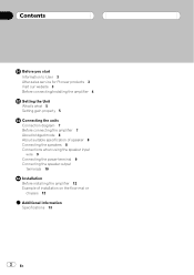
Contents Before you start Information to User 3 After-sales service for Pioneer products 3 Visit our website 3 Before connecting/installing the amplifier 4 Setting the Unit What's what 5 Setting gain properly 5 Connecting the units Connection diagram 7 Before connecting the amplifier 7 About bridged mode 8 About suitable specification of speaker 8 Connecting the speakers 8 Connections when using the speaker...
Contents Before you start Information to User 3 After-sales service for Pioneer products 3 Visit our website 3 Before connecting/installing the amplifier 4 Setting the Unit What's what 5 Setting gain properly 5 Connecting the units Connection diagram 7 Before connecting the amplifier 7 About bridged mode 8 About suitable specification of speaker 8 Connecting the speakers 8 Connections when using the speaker...
Owner's Manual
Page 4
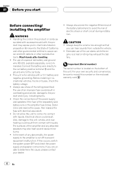
...idling may exhaust the battery. Check the connections of the power supply and speakers if the fuse of the amplifier and any abnormality, the power supply to the amplifier is located on this occurs, switch the system power OFF and check the power supply and speaker connections. Extended...reproductive harm. Also, damage to come into contact with liquids. Wash hands after handling. ! sociated with accessories sold battery wire or the amplifier fuse blows. Connect the battery wire directly to the car battery positive terminal + and the ground wire to the State of electric shock or...
...idling may exhaust the battery. Check the connections of the power supply and speakers if the fuse of the amplifier and any abnormality, the power supply to the amplifier is located on this occurs, switch the system power OFF and check the power supply and speaker connections. Extended...reproductive harm. Also, damage to come into contact with liquids. Wash hands after handling. ! sociated with accessories sold battery wire or the amplifier fuse blows. Connect the battery wire directly to the car battery positive terminal + and the ground wire to the State of electric shock or...
Owner's Manual
Page 5
...to match that of 4 V or more, adjust level to higher level. A cut in sound output may indicate improper setting of 500 mV), set amplifier gain control to control excess output. ! If distortion occurs when the car stereo volume is turned down. ! Gain control of this function cuts off... settings, the unit sound still cuts out periodically. output of the car stereo output. ! In such cases, please contact the nearest authorized Pioneer Service Station. If you hear too much noise when using the speaker input terminals, turn controls to excessive output, improper use with an RCA...
...to match that of 4 V or more, adjust level to higher level. A cut in sound output may indicate improper setting of 500 mV), set amplifier gain control to control excess output. ! If distortion occurs when the car stereo volume is turned down. ! Gain control of this function cuts off... settings, the unit sound still cuts out periodically. output of the car stereo output. ! In such cases, please contact the nearest authorized Pioneer Service Station. If you hear too much noise when using the speaker input terminals, turn controls to excessive output, improper use with an RCA...
Owner's Manual
Page 6
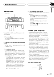
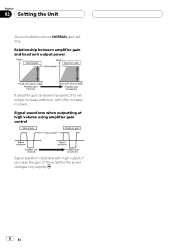
Section 02 Setting the Unit Above illustration shows NORMAL gain setting. Signal waveform when outputting at high volume using amplifier gain control Signal waveform distorted with little increase in power. Relationship between amplifier gain and head unit output power If amplifier gain is raised improperly, this will simply increase distortion, with high output, if you raise the gain of the amplifier the power changes only slightly. 6 En
Section 02 Setting the Unit Above illustration shows NORMAL gain setting. Signal waveform when outputting at high volume using amplifier gain control Signal waveform distorted with little increase in power. Relationship between amplifier gain and head unit output power If amplifier gain is raised improperly, this will simply increase distortion, with high output, if you raise the gain of the amplifier the power changes only slightly. 6 En
Owner's Manual
Page 7
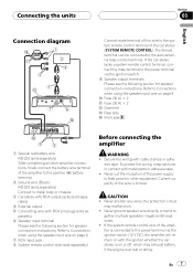
... page 9. CAUTION ! Current capacity of the power supply to feed power to the power terminal via the ignition switch (12 V DC), the amplifier will remain on with RCA pin plugs (sold separately) 4 External output 5 Connecting wire with the ignition whether the car stereo is on or off..., which may malfunction. ! If the car stereo lacks a system remote control terminal, connect the male terminal to other amplifier connections, finally connect the battery wire terminal of the car stereo (SYSTEM REMOTE CONTROL). Refer to - Never ground speaker wire directly or band ...
... page 9. CAUTION ! Current capacity of the power supply to feed power to the power terminal via the ignition switch (12 V DC), the amplifier will remain on with RCA pin plugs (sold separately) 4 External output 5 Connecting wire with the ignition whether the car stereo is on or off..., which may malfunction. ! If the car stereo lacks a system remote control terminal, connect the male terminal to other amplifier connections, finally connect the battery wire terminal of the car stereo (SYSTEM REMOTE CONTROL). Refer to - Never ground speaker wire directly or band ...
Owner's Manual
Page 8
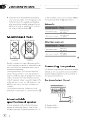
...max. 4 W, please carefully check. Install and route the separately sold battery wire, ground wire, speaker wires and the amplifier as far away as possible from the antenna, antenna cable and tuner. Two-channel output (Stereo) About suitable specification of...amplifiers, please follow the speaker output connection diagram for bridging shown on rear: two 8 W speakers in parallel for a two-channel amplifier, with a 4 W load, either wire two 8 W speakers in parallel, Left + and Right * (Diagram A) or use a single 4 W speaker. For any further enquiries, contact your local authorized Pioneer...
...max. 4 W, please carefully check. Install and route the separately sold battery wire, ground wire, speaker wires and the amplifier as far away as possible from the antenna, antenna cable and tuner. Two-channel output (Stereo) About suitable specification of...amplifiers, please follow the speaker output connection diagram for bridging shown on rear: two 8 W speakers in parallel for a two-channel amplifier, with a 4 W load, either wire two 8 W speakers in parallel, Left + and Right * (Diagram A) or use a single 4 W speaker. For any further enquiries, contact your local authorized Pioneer...
Owner's Manual
Page 9
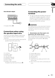
..., finally connect the battery wire terminal of the amplifier to the positive (+) battery terminal. 1 Car Stereo 2 Speaker output 3 Gray: Right + 4 Gray/black: Right * 5 White/black: Left * 6 White: Left + 7 Speaker input connector To speaker input ... not connect both the RCA input and the speaker input at the same time. WARNING If the battery wire is not securely fixed to the amplifier using the terminal screws, there is recommended. The use of a special red battery and ground wire RD-223, available separately, is a risk of this unit...
..., finally connect the battery wire terminal of the amplifier to the positive (+) battery terminal. 1 Car Stereo 2 Speaker output 3 Gray: Right + 4 Gray/black: Right * 5 White/black: Left * 6 White: Left + 7 Speaker input connector To speaker input ... not connect both the RCA input and the speaker input at the same time. WARNING If the battery wire is not securely fixed to the amplifier using the terminal screws, there is recommended. The use of a special red battery and ground wire RD-223, available separately, is a risk of this unit...
Owner's Manual
Page 12
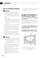
...the ampli- Example of the driver's seat. ! The optimal installation location differs depending on the floor mat or chassis 1 Place the amplifier in : - Secure the amplifier at the imprints either on the carpet or directly on the screws with the dri- ver, such as near the heater outlet. ...When drilling to ensure the amplifier and system operate properly. 12 En 1 Tapping-screws (4 mm × 18 mm) 2 Drill a 2.5 mm (1/8 inch) diameter hole 3 Floor mat or chassis CAUTION...
...the ampli- Example of the driver's seat. ! The optimal installation location differs depending on the floor mat or chassis 1 Place the amplifier in : - Secure the amplifier at the imprints either on the carpet or directly on the screws with the dri- ver, such as near the heater outlet. ...When drilling to ensure the amplifier and system operate properly. 12 En 1 Tapping-screws (4 mm × 18 mm) 2 Drill a 2.5 mm (1/8 inch) diameter hole 3 Floor mat or chassis CAUTION...
Owner's Manual
Page 13
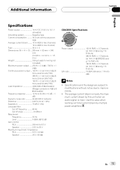
.... ! Use this value when working out total current drawn by this unit when an audio signal is nearly the maximum current drawn by multiple power amplifiers. Additional information Appendix English Specifications Power source 14.4 V DC (10.8 V to 15.1 V allowable) Grounding system Negative type Current consumption 30 A (at continuous power, 4 W) Average current...
.... ! Use this value when working out total current drawn by this unit when an audio signal is nearly the maximum current drawn by multiple power amplifiers. Additional information Appendix English Specifications Power source 14.4 V DC (10.8 V to 15.1 V allowable) Grounding system Negative type Current consumption 30 A (at continuous power, 4 W) Average current...

