Owner's Manual
Page 2
Contents Before you start Information to User 3 After-sales service for Pioneer products 3 Visit our website 3 Before connecting/installing the amplifier 4 Setting the Unit What's what 5 Setting gain properly 5 Connecting the units Connection diagram 7 Before connecting the amplifier 7 About bridged mode 8 About suitable specification of speaker 8 Connecting the speakers 8 Connections when using the speaker input wire 9 Connecting the power terminal 9 Connecting the speaker output terminals 10 Installation Before installing the amplifier 12 Example of installation on the floor mat or chassis ...
Contents Before you start Information to User 3 After-sales service for Pioneer products 3 Visit our website 3 Before connecting/installing the amplifier 4 Setting the Unit What's what 5 Setting gain properly 5 Connecting the units Connection diagram 7 Before connecting the amplifier 7 About bridged mode 8 About suitable specification of speaker 8 Connecting the speakers 8 Connections when using the speaker input wire 9 Connecting the power terminal 9 Connecting the speaker output terminals 10 Installation Before installing the amplifier 12 Example of installation on the floor mat or chassis ...
Owner's Manual
Page 3
... or theft. 2 Receive updates on the latest products and technologies. 3 Download owner's manuals, order product catalogues, research new products, and much more. We will keep the details of Canada, Inc. Pioneer Electronics (USA) Inc. Box 1760 Long Beach, CA 90801-1760 800-421-1404 CANADA Pioneer Electronics of your nearest Pioneer authorized dealer or installation specialist. CUSTOMER SUPPORT DIVISION P.O. En 3
... or theft. 2 Receive updates on the latest products and technologies. 3 Download owner's manuals, order product catalogues, research new products, and much more. We will keep the details of Canada, Inc. Pioneer Electronics (USA) Inc. Box 1760 Long Beach, CA 90801-1760 800-421-1404 CANADA Pioneer Electronics of your nearest Pioneer authorized dealer or installation specialist. CUSTOMER SUPPORT DIVISION P.O. En 3
Owner's Manual
Page 4
... cord on this occurs, switch the system power OFF and check the power supply and speaker connections. Determine and resolve the cause, then replace the fuse with a 12 V battery and negative grounding. If you can hear sounds from contact with liquids. Always disconnect the negative * terminal of the battery beforehand to record this unit. gine is cut off to the car body. ! Wash hands after...
... cord on this occurs, switch the system power OFF and check the power supply and speaker connections. Determine and resolve the cause, then replace the fuse with a 12 V battery and negative grounding. If you can hear sounds from contact with liquids. Always disconnect the negative * terminal of the battery beforehand to record this unit. gine is cut off to the car body. ! Wash hands after...
Owner's Manual
Page 5
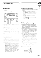
When the Subwoofer is connected: Select OFF. Setting gain properly ! When outputting high volume sound etc., this unit Preout level: 2 V (Standard: 500mV) En 5 To ensure continuous sound output with the head unit at a high volume, set to indicate power ON. 2 BASS BOOST (bass boost level control) switch You can remain unchanged and to higher level. When the full range speaker is connected: Select ON. In such cases, please contact the nearest authorized Pioneer Service Station. For use a flathead screwdriver if needed. 1 Power indicator The power indicator lights up to...
When the Subwoofer is connected: Select OFF. Setting gain properly ! When outputting high volume sound etc., this unit Preout level: 2 V (Standard: 500mV) En 5 To ensure continuous sound output with the head unit at a high volume, set to indicate power ON. 2 BASS BOOST (bass boost level control) switch You can remain unchanged and to higher level. When the full range speaker is connected: Select ON. In such cases, please contact the nearest authorized Pioneer Service Station. For use a flathead screwdriver if needed. 1 Power indicator The power indicator lights up to...
Owner's Manual
Page 6
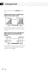
Signal waveform when outputting at high volume using amplifier gain control Signal waveform distorted with little increase in power. Relationship between amplifier gain and head unit output power If amplifier gain is raised improperly, this will simply increase distortion, with high output, if you raise the gain of the amplifier the power changes only slightly. 6 En Section 02 Setting the Unit Above illustration shows NORMAL gain setting.
Signal waveform when outputting at high volume using amplifier gain control Signal waveform distorted with little increase in power. Relationship between amplifier gain and head unit output power If amplifier gain is raised improperly, this will simply increase distortion, with high output, if you raise the gain of the amplifier the power changes only slightly. 6 En Section 02 Setting the Unit Above illustration shows NORMAL gain setting.
Owner's Manual
Page 7
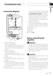
... English Connection diagram Connect male terminal of this wire to the system remote control terminal of the amplifier is connected to the power terminal via the ignition switch. 9 Speaker output terminals Please see the following section for speaker connection instructions. The female terminal can be connected to - Current capacity of the amplifier to the positive (+) battery terminal. 2 Ground wire (Black) RD-223 (sold separately) Connect to Connections when using the speaker input wire on page 9. En 7 Refer to metal body or chassis. 3 Car stereo with RCA output...
... English Connection diagram Connect male terminal of this wire to the system remote control terminal of the amplifier is connected to the power terminal via the ignition switch. 9 Speaker output terminals Please see the following section for speaker connection instructions. The female terminal can be connected to - Current capacity of the amplifier to the positive (+) battery terminal. 2 Ground wire (Black) RD-223 (sold separately) Connect to Connections when using the speaker input wire on page 9. En 7 Refer to metal body or chassis. 3 Car stereo with RCA output...
Owner's Manual
Page 8
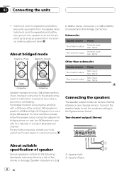
...For bridged mode for a 4 W load or a single 4 W speaker per channel. Connecting the speakers The speaker output mode can be two-channel (stereo) or one-channel (mono). Section 03 Connecting the units ! For other bridge connection. Install and route the separately sold battery wire as far as possible from the antenna, antenna cable and tuner. Subwoofer Speaker channel Two-channel output One-channel output Power Nominal input: Min. 135 W Nominal input: Min. 420 W Other than subwoofer Speaker channel Two-channel output One-channel output Power MAX input: Min. 250 W MAX input: Min...
...For bridged mode for a 4 W load or a single 4 W speaker per channel. Connecting the speakers The speaker output mode can be two-channel (stereo) or one-channel (mono). Section 03 Connecting the units ! For other bridge connection. Install and route the separately sold battery wire as far as possible from the antenna, antenna cable and tuner. Subwoofer Speaker channel Two-channel output One-channel output Power Nominal input: Min. 135 W Nominal input: Min. 420 W Other than subwoofer Speaker channel Two-channel output One-channel output Power MAX input: Min. 250 W MAX input: Min...
Owner's Manual
Page 9
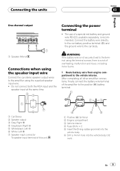
... not connect both the RCA input and the speaker input at the same time. Connecting the units Section 03 English One-channel output Connecting the power terminal ! Connect the battery wire directly to the car battery positive terminal (+) and the ground wire to the car body. 1 Speaker (Mono) Connections when using the speaker input wire Connect the car stereo speaker output wires to the positive (+) battery terminal. 1 Car Stereo 2 Speaker output 3 Gray: Right + 4 Gray/black: Right * 5 White/black: Left * 6 White: Left + 7 Speaker input connector To speaker input terminal of overheating...
... not connect both the RCA input and the speaker input at the same time. Connecting the units Section 03 English One-channel output Connecting the power terminal ! Connect the battery wire directly to the car battery positive terminal (+) and the ground wire to the car body. 1 Speaker (Mono) Connections when using the speaker input wire Connect the car stereo speaker output wires to the positive (+) battery terminal. 1 Car Stereo 2 Speaker output 3 Gray: Right + 4 Gray/black: Right * 5 White/black: Left * 6 White: Left + 7 Speaker input connector To speaker input terminal of overheating...
Owner's Manual
Page 10
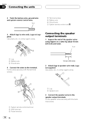
... remote control terminal 2 GND terminal 3 Power terminal 10 En 1 Lug 2 Speaker wire 3 Connect the speaker wires to wires. Fix the speaker wires securely with the terminal screws. 2 Attach lugs to speaker wire ends. Fix the wires securely with the terminal screws. Connecting the speaker output terminals 1 Expose the end of the speaker wires using nippers or a cutter by about 10 mm (3/8 inch) and twist. Section 03 Connecting the units 2 Twist the battery wire, ground wire and system remote control wire. Twist 4 Terminal screws 5 Battery wire 6 Ground wire 7 System remote control...
... remote control terminal 2 GND terminal 3 Power terminal 10 En 1 Lug 2 Speaker wire 3 Connect the speaker wires to wires. Fix the speaker wires securely with the terminal screws. 2 Attach lugs to speaker wire ends. Fix the wires securely with the terminal screws. Connecting the speaker output terminals 1 Expose the end of the speaker wires using nippers or a cutter by about 10 mm (3/8 inch) and twist. Section 03 Connecting the units 2 Twist the battery wire, ground wire and system remote control wire. Twist 4 Terminal screws 5 Battery wire 6 Ground wire 7 System remote control...
Owner's Manual
Page 11
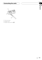
Connecting the units 1 Terminal screws 2 Speaker wires 3 Speaker output terminals English Section 03 En 11
Connecting the units 1 Terminal screws 2 Speaker wires 3 Speaker output terminals English Section 03 En 11
Owner's Manual
Page 12
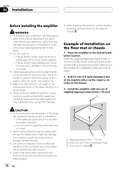
... directly on the floor mat or chassis 1 Place the amplifier in : - Insert the supplied tapping screws (4 mm × 18 mm) into the screw holes and push on the screws with the use the supplied parts in a short-circuit through hot areas, such as on the car model. fuel/brake lines, wiring) from being cut by vibration of supplied tapping screws (4 mm × 18 mm). Make...
... directly on the floor mat or chassis 1 Place the amplifier in : - Insert the supplied tapping screws (4 mm × 18 mm) into the screw holes and push on the screws with the use the supplied parts in a short-circuit through hot areas, such as on the car model. fuel/brake lines, wiring) from being cut by vibration of supplied tapping screws (4 mm × 18 mm). Make...
Owner's Manual
Page 13
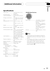
... pass filter: Cut off frequency 80 Hz Cut off slope 12 dB/oct Bass boost: Frequency 50 Hz Level 0 dB/6 dB/12 dB Gain control: RCA 200 mV to 6.5 V Speaker 0.8 V to improvements. ! En 13 Additional information Appendix English Specifications Power source 14.4 V DC (10.8 V to 15.1 V allowable) Grounding system Negative type Current consumption 30 A (at continuous power, 4 W) Average current drawn ......... 10 A (4 W for two channels) 19 A (4 W for one channel) Fuse...
... pass filter: Cut off frequency 80 Hz Cut off slope 12 dB/oct Bass boost: Frequency 50 Hz Level 0 dB/6 dB/12 dB Gain control: RCA 200 mV to 6.5 V Speaker 0.8 V to improvements. ! En 13 Additional information Appendix English Specifications Power source 14.4 V DC (10.8 V to 15.1 V allowable) Grounding system Negative type Current consumption 30 A (at continuous power, 4 W) Average current drawn ......... 10 A (4 W for two channels) 19 A (4 W for one channel) Fuse...
Owner's Manual
Page 40
...OF CANADA, INC. 300 Allstate Parkway, Markham, Ontario L3R 0P2, Canada TEL: 1-877-283-5901 TEL: 905-479-4411 PIONEER ELECTRONICS DE MEXICO, S.A. Blvd.Manuel Avila Camacho 138 10 piso Col.Lomas de Chapultepec, Mexico, D.F. 11000 TEL: 55-...4270 44號13 02) 2521-3588 9樓901-6 0852) 2848-6488 Published by Pioneer Corporation. de C.V. PIONEER CORPORATION 4-1, MEGURO 1-CHOME, MEGURO-KU TOKYO 153-8654, JAPAN PIONEER ELECTRONICS (USA) INC. P.O. Copyright © 2008 par Pioneer Corporation. All rights reserved. Box 1540, Long Beach, California 90801-1540, U.S.A. TEL: ...
...OF CANADA, INC. 300 Allstate Parkway, Markham, Ontario L3R 0P2, Canada TEL: 1-877-283-5901 TEL: 905-479-4411 PIONEER ELECTRONICS DE MEXICO, S.A. Blvd.Manuel Avila Camacho 138 10 piso Col.Lomas de Chapultepec, Mexico, D.F. 11000 TEL: 55-...4270 44號13 02) 2521-3588 9樓901-6 0852) 2848-6488 Published by Pioneer Corporation. de C.V. PIONEER CORPORATION 4-1, MEGURO 1-CHOME, MEGURO-KU TOKYO 153-8654, JAPAN PIONEER ELECTRONICS (USA) INC. P.O. Copyright © 2008 par Pioneer Corporation. All rights reserved. Box 1540, Long Beach, California 90801-1540, U.S.A. TEL: ...


