
Service Manual
Page 1
... 1. PCB CONNECTION DIAGRAM 12 5. ADJUSTMENT 20 7. PIONEER ELECTRONIC [EUROPE] N.V. OPERATIONS AND SPECIFICATIONS 23 PIONEER ELECTRONIC CORPORATION 4-1, Meguro 1-Chome, Meguro-ku, Tokyo 153-8654, Japan PIONEER ELECTRONICS SERVICE INC. SCHEMATIC DIAGRAM 6 4. JAN. 1999 Printed in Japan ELECTRICAL PARTS LIST 16 6. GM-X434/X1R/UC BRIDGEABLE FOUR-CHANNEL POWER AMPLIFIER GM-X434 GM-X334 X1R/UC,EW,ES ORDER NO.
... 1. PCB CONNECTION DIAGRAM 12 5. ADJUSTMENT 20 7. PIONEER ELECTRONIC [EUROPE] N.V. OPERATIONS AND SPECIFICATIONS 23 PIONEER ELECTRONIC CORPORATION 4-1, Meguro 1-Chome, Meguro-ku, Tokyo 153-8654, Japan PIONEER ELECTRONICS SERVICE INC. SCHEMATIC DIAGRAM 6 4. JAN. 1999 Printed in Japan ELECTRICAL PARTS LIST 16 6. GM-X434/X1R/UC BRIDGEABLE FOUR-CHANNEL POWER AMPLIFIER GM-X434 GM-X334 X1R/UC,EW,ES ORDER NO.
Service Manual
Page 3
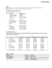
... 8 Cord Assy 9 Cord(Remote) 10 Cord(Power) 11 Cord(Ground) See Contrast table(2) See Contrast table(2) See Contrast table(2) See Contrast table(2) See Contrast table(2) (2) CONTRAST TABLE GM-X434/X1R/UC, GM-X334/X1R/UC, GM-X334/X1R/EW and GM-X334/X1R/ES are used for the following: Mark ..., Spanish Portuguese(B), Arabic 3 GM-X334/X1R/UC GM-X334/X1R/EW HHG0175 HHG0177 HHL0175 HHL0177 HRD0074 HRD0076 Not used Not used Not used HRY1087 GM-X334/X1R/ES HHG0178 HHL0178 HRD0077 HRD0078 Not used * 7-4 Card * 7-5 PRC 8 Cord Assy 9 Cord(Remote) 10 Cord(Power) Not used HRY0007 Not used...
... 8 Cord Assy 9 Cord(Remote) 10 Cord(Power) 11 Cord(Ground) See Contrast table(2) See Contrast table(2) See Contrast table(2) See Contrast table(2) See Contrast table(2) (2) CONTRAST TABLE GM-X434/X1R/UC, GM-X334/X1R/UC, GM-X334/X1R/EW and GM-X334/X1R/ES are used for the following: Mark ..., Spanish Portuguese(B), Arabic 3 GM-X334/X1R/UC GM-X334/X1R/EW HHG0175 HHG0177 HHL0175 HHL0177 HRD0074 HRD0076 Not used Not used Not used HRY1087 GM-X334/X1R/ES HHG0178 HHL0178 HRD0077 HRD0078 Not used * 7-4 Card * 7-5 PRC 8 Cord Assy 9 Cord(Remote) 10 Cord(Power) Not used HRY0007 Not used...

Service Manual
Page 23
...controls counterclockwise. • If you hear too much noise when using with an RCA equipped Pioneer car stereo with the bass boost control. • Bass Boost Level Control, Bass Boost ...mV), set to the MIN position. • If you only use . Power Indicator The power indicator lights when the power is not necessary for the speaker you want to cut the verylow-frequency ...be adjusted only when the LPF/HPF select switch is turned up , turn these controls clockwise. GM-X434,X334 23 Input Select Switch For two-channel input, slide this switch to the "NORMAL" position. output...
...controls counterclockwise. • If you hear too much noise when using with an RCA equipped Pioneer car stereo with the bass boost control. • Bass Boost Level Control, Bass Boost ...mV), set to the MIN position. • If you only use . Power Indicator The power indicator lights when the power is not necessary for the speaker you want to cut the verylow-frequency ...be adjusted only when the LPF/HPF select switch is turned up , turn these controls clockwise. GM-X434,X334 23 Input Select Switch For two-channel input, slide this switch to the "NORMAL" position. output...
Service Manual
Page 24
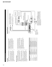
... 12-volt battery and negative grounding. If the car stereo does not have a system remote control terminal, connect the male terminal to the power terminal through the ignition switch (12 V DC), the amplifier will occur to metal body or chassis. Before installing it in a short-circuit...• Speakers to be 1 to 8 ohms. (2 to 8 Ω for a long time while the engine is connected to the power terminal through the ignition switch. GM-X434,X334 24 Connecting the Unit CAUTION • Remove the negative (-) terminal of the battery to avoid the risk of short-circuit and damage...
... 12-volt battery and negative grounding. If the car stereo does not have a system remote control terminal, connect the male terminal to the power terminal through the ignition switch (12 V DC), the amplifier will occur to metal body or chassis. Before installing it in a short-circuit...• Speakers to be 1 to 8 ohms. (2 to 8 Ω for a long time while the engine is connected to the power terminal through the ignition switch. GM-X434,X334 24 Connecting the Unit CAUTION • Remove the negative (-) terminal of the battery to avoid the risk of short-circuit and damage...

Service Manual
Page 25
... maximum current drawn by this value when working out total current drawn by multiple power amplifiers. 25 GM-X434/X1R/UC, GM-X334/X1R/UC, GM-X334/X1R/EW, GM-X334/X1R/ES Specifications Power source ...14.4 V DC (10.8 - 15.1 V allowable) Grounding system ......Negative type Current consumption ...18 A (at continuous power, 4 Ω) Average current drawn* ...5.5 A (4 Ω for four channels) 10 A (4 Ω for two channels) Fuse ...25 A ...
... maximum current drawn by this value when working out total current drawn by multiple power amplifiers. 25 GM-X434/X1R/UC, GM-X334/X1R/UC, GM-X334/X1R/EW, GM-X334/X1R/ES Specifications Power source ...14.4 V DC (10.8 - 15.1 V allowable) Grounding system ......Negative type Current consumption ...18 A (at continuous power, 4 Ω) Average current drawn* ...5.5 A (4 Ω for four channels) 10 A (4 Ω for two channels) Fuse ...25 A ...

