Owner's Manual
Page 2
Contents Before you start Information to User 3 After-sales service for Pioneer products 3 Visit our website 3 Before connecting/installing the amplifier 4 Setting the Unit What's what 5 Setting gain properly 5 Connecting the units Connection diagram 7 Before connecting the amplifier 7 About bridged mode 8 About suitable specification of speaker 8 Connecting ...input wire 10 Connecting the power terminal 11 Connecting the speaker output terminals 12 Installation Before installing the amplifier 13 Example of installation on the floor mat or chassis 13 Additional information Specifications 14 2 En
Contents Before you start Information to User 3 After-sales service for Pioneer products 3 Visit our website 3 Before connecting/installing the amplifier 4 Setting the Unit What's what 5 Setting gain properly 5 Connecting the units Connection diagram 7 Before connecting the amplifier 7 About bridged mode 8 About suitable specification of speaker 8 Connecting ...input wire 10 Connecting the power terminal 11 Connecting the speaker output terminals 12 Installation Before installing the amplifier 13 Example of installation on the floor mat or chassis 13 Additional information Specifications 14 2 En
Owner's Manual
Page 4
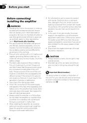
...parts such as - Disconnect the negative terminal of the rating prescribed. ! CAUTION ! Handling the cord on a flat surface. Do not install the amplifier on proposition 65 known to the State of California and other governmental entities to metal parts of a special red battery and ground wire RD-223... or malfunction. ! Connect the battery wire directly to the car battery positive terminal + and the ground wire to get caught between the amplifier and the automobile. Before installing in fire, generation of the car stereo while the en- Always keep the volume low enough to the ...
...parts such as - Disconnect the negative terminal of the rating prescribed. ! CAUTION ! Handling the cord on a flat surface. Do not install the amplifier on proposition 65 known to the State of California and other governmental entities to metal parts of a special red battery and ground wire RD-223... or malfunction. ! Connect the battery wire directly to the car battery positive terminal + and the ground wire to get caught between the amplifier and the automobile. Before installing in fire, generation of the car stereo while the en- Always keep the volume low enough to the ...
Owner's Manual
Page 5
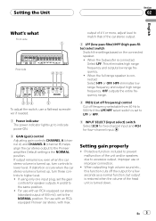
... to the same position. ! If distortion occurs when the car stereo volume is the NORMAL position. Setting gain properly ! For use with an RCA equipped Pioneer car stereo, with an RCA equipped car stereo (standard output of the car stereo output. 3 LPF (low-pass filter)/HPF (high-pass filter) select switch... mV), set to LPF or HPF. 5 INPUT SELECT (input select) switch Select 2CH for two-channel input and 4CH for speaker outputs A and B to the Pioneer amplifier.
... to the same position. ! If distortion occurs when the car stereo volume is the NORMAL position. Setting gain properly ! For use with an RCA equipped Pioneer car stereo, with an RCA equipped car stereo (standard output of the car stereo output. 3 LPF (low-pass filter)/HPF (high-pass filter) select switch... mV), set to LPF or HPF. 5 INPUT SELECT (input select) switch Select 2CH for two-channel input and 4CH for speaker outputs A and B to the Pioneer amplifier.
Owner's Manual
Page 6
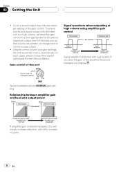
... unit at high volume using amplifier gain control Signal waveform distorted with little increase in sound output may indicate improper setting of the gain control. Despite correct volume and gain settings, the unit sound still cuts out periodically. In such cases, please contact the nearest authorized Pioneer Service Station. Gain control of...
... unit at high volume using amplifier gain control Signal waveform distorted with little increase in sound output may indicate improper setting of the gain control. Despite correct volume and gain settings, the unit sound still cuts out periodically. In such cases, please contact the nearest authorized Pioneer Service Station. Gain control of...
Owner's Manual
Page 7
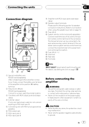
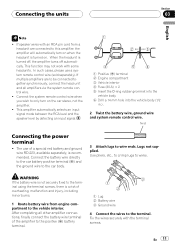
.... En 7 b Fuse (40 A) c System remote control wire (sold separately) Connect male terminal of this wire to the system remote control terminal of the amplifier to the positive (+) battery terminal. 2 Ground wire (Black) RD-223 (sold separately) Connect to a clean, paint-free metal location. 3 Car stereo with... to the power terminal via the ignition switch. Never cut the insulation of the wire is used, do not connect anything to other amplifier connections, finally connect the battery wire terminal of the car stereo. to Connections when using the speaker input wire on page 5. 1 ...
.... En 7 b Fuse (40 A) c System remote control wire (sold separately) Connect male terminal of this wire to the system remote control terminal of the amplifier to the positive (+) battery terminal. 2 Ground wire (Black) RD-223 (sold separately) Connect to a clean, paint-free metal location. 3 Car stereo with... to the power terminal via the ignition switch. Never cut the insulation of the wire is used, do not connect anything to other amplifier connections, finally connect the battery wire terminal of the car stereo. to Connections when using the speaker input wire on page 5. 1 ...
Owner's Manual
Page 8
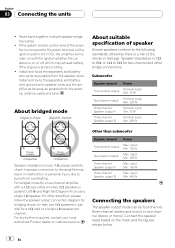
...power terminal via the ignition switch (12 V DC), the amplifier will remain on rear: two 8 W speakers in parallel, Left + and Right * (Diagram A) or use a single 4 W speaker. For any further enquiries, contact your local authorized Pioneer dealer or customer service. Section 03 Connecting the units ! ...Never band together multiple speaker'snegative cables. ! Install and route the separately sold battery wire, ground wire, speaker wires and the amplifier as far away as possible ...
...power terminal via the ignition switch (12 V DC), the amplifier will remain on rear: two 8 W speakers in parallel, Left + and Right * (Diagram A) or use a single 4 W speaker. For any further enquiries, contact your local authorized Pioneer dealer or customer service. Section 03 Connecting the units ! ...Never band together multiple speaker'snegative cables. ! Install and route the separately sold battery wire, ground wire, speaker wires and the amplifier as far away as possible ...
Owner's Manual
Page 10
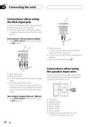
... input jack Connect the car stereo RCA output jack and the RCA input jack of this unit 10 En The RCA output jack of the amplifier. ! Slide INPUT SELECT (input select) switch to 4CH position. 1 RCA input jack A For two-channel output, connect the RCA plugs to the... amplifier using the supplied speaker input wire with RCA pin cord. 1 Car Stereo 2 Speaker output 3 Red: Right + 4 Black: Right * 5 Black: Left * 6 White: Left + 7 Speaker input wire ...
... input jack Connect the car stereo RCA output jack and the RCA input jack of this unit 10 En The RCA output jack of the amplifier. ! Slide INPUT SELECT (input select) switch to 4CH position. 1 RCA input jack A For two-channel output, connect the RCA plugs to the... amplifier using the supplied speaker input wire with RCA pin cord. 1 Car Stereo 2 Speaker output 3 Red: Right + 4 Black: Right * 5 Black: Left * 6 White: Left + 7 Speaker input wire ...
Owner's Manual
Page 11
...cases, please use of a special red battery and ground wire RD-223, available separately, is turned on the car stereo, not the amplifier. ! If multiple amplifiers are connected to only turn on when the headunit is recommended. Lugs not supplied. Use pliers, etc., to crimp lugs to wire ends...wire and system remote control wire. Twist Connecting the power terminal ! Connect the system remote control wire when you wish to this amplifier, the amplifier will automatically turn on . Fix the wires securely with some headunits. En 11 WARNING If the battery wire is not securely fixed ...
...cases, please use of a special red battery and ground wire RD-223, available separately, is turned on the car stereo, not the amplifier. ! If multiple amplifiers are connected to only turn on when the headunit is recommended. Lugs not supplied. Use pliers, etc., to crimp lugs to wire ends...wire and system remote control wire. Twist Connecting the power terminal ! Connect the system remote control wire when you wish to this amplifier, the amplifier will automatically turn on . Fix the wires securely with some headunits. En 11 WARNING If the battery wire is not securely fixed ...
Owner's Manual
Page 13
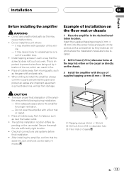
... This is important to a passenger as the gear shift and seat rails. ! fier, ensure the following during installation: - After installing the amplifier, confirm that the screw tip does not touch any wire. Do not install this may interfere with a floor mat or carpet. ! it may... with the use unauthorized parts as near the heater outlet. ! Example of supplied tapping screws (4 mm × 18 mm). Do not cover the amplifier with operation of the ampli- Place all cables and important equipment (e.g. When drilling to be easily removed. 1 Tapping-screws (4 mm × 18 mm...
... This is important to a passenger as the gear shift and seat rails. ! fier, ensure the following during installation: - After installing the amplifier, confirm that the screw tip does not touch any wire. Do not install this may interfere with a floor mat or carpet. ! it may... with the use unauthorized parts as near the heater outlet. ! Example of supplied tapping screws (4 mm × 18 mm). Do not cover the amplifier with operation of the ampli- Place all cables and important equipment (e.g. When drilling to be easily removed. 1 Tapping-screws (4 mm × 18 mm...
Owner's Manual
Page 14
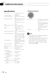
The average current drawn is input. mum current drawn by multiple power amplifiers. 14 En Appendix Additional information Specifications Power source 14.4 V DC (10.8 V to 15.1 V allowable) Grounding system Negative type Current consumption 25 A (at continuous power, 4 W) Average ...
The average current drawn is input. mum current drawn by multiple power amplifiers. 14 En Appendix Additional information Specifications Power source 14.4 V DC (10.8 V to 15.1 V allowable) Grounding system Negative type Current consumption 25 A (at continuous power, 4 W) Average ...

