Owner's Manual
Page 3
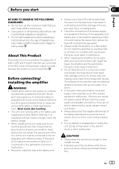
... known to the State of California and other governmental entities to cause cancer and birth defect or other malfunction. Before connecting/ installing the amplifier WARNING ! Wash hands after handling. ! This unit is properly connected to metal parts of the car's body. Always use headphones while...up and cause minor burns. ! Use caution or temporarily discontinue use of the separately sold with accessories sold battery wire or the amplifier fuse blows. sociated with the product may exhaust the battery. Determine and resolve the cause, then replace the fuse with different ...
... known to the State of California and other governmental entities to cause cancer and birth defect or other malfunction. Before connecting/ installing the amplifier WARNING ! Wash hands after handling. ! This unit is properly connected to metal parts of the car's body. Always use headphones while...up and cause minor burns. ! Use caution or temporarily discontinue use of the separately sold with accessories sold battery wire or the amplifier fuse blows. sociated with the product may exhaust the battery. Determine and resolve the cause, then replace the fuse with different ...
Owner's Manual
Page 4
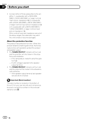
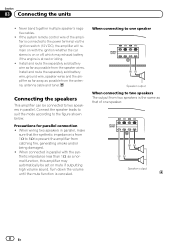
... number is applied to protect the product and speaker output. ! The POWER/PROTECT indicator will turn red and the amplifier will operate to the speaker output terminal. ! If the speaker output terminal and speaker wire are out of three subwoofers...output will be sure to the amplifier; 1: a subwoofer with a 300 W (GMD8601) / 500 W (GM-D9601) or larger nominal input and an impedance 4 W, 2: a subwoofer with a 500 W (GM-D8601) / 800 W (GM-D9601) or larger nominal input and an impedance 2 W or 3: a subwoofer with a 800 W (GM-D8601) / 1 200 W (GM-D9601) or larger nominal input ...
... number is applied to protect the product and speaker output. ! The POWER/PROTECT indicator will turn red and the amplifier will operate to the speaker output terminal. ! If the speaker output terminal and speaker wire are out of three subwoofers...output will be sure to the amplifier; 1: a subwoofer with a 300 W (GMD8601) / 500 W (GM-D9601) or larger nominal input and an impedance 4 W, 2: a subwoofer with a 500 W (GM-D8601) / 800 W (GM-D9601) or larger nominal input and an impedance 2 W or 3: a subwoofer with a 800 W (GM-D8601) / 1 200 W (GM-D9601) or larger nominal input ...
Owner's Manual
Page 5
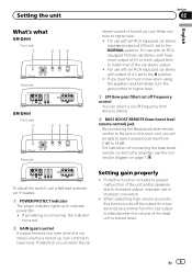
For use with an RCA equipped Pioneer car stereo, with maximum output of 4 V or more, adjust level to match that of the ... up , turn these controls to higher level. ! En 5 Setting the unit Section 02 English What's what GM-D8601 Front side 1 23 4 Rear side GM-D9601 Front side 1 23 4 Rear side stereo volume is turned up , turn controls to lower level. For...speaker input terminals, turn the gain control to indicate power ON. ! For instruction of 4 V, set to the amplifier, see the Connection diagram on the main unit, you will be able to select a bass boost level from 0 dB to the ...
For use with an RCA equipped Pioneer car stereo, with maximum output of 4 V or more, adjust level to match that of the ... up , turn these controls to higher level. ! En 5 Setting the unit Section 02 English What's what GM-D8601 Front side 1 23 4 Rear side GM-D9601 Front side 1 23 4 Rear side stereo volume is turned up , turn controls to lower level. For...speaker input terminals, turn the gain control to indicate power ON. ! For instruction of 4 V, set to the amplifier, see the Connection diagram on the main unit, you will be able to select a bass boost level from 0 dB to the ...
Owner's Manual
Page 6
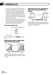
... power changes only slightly. To ensure continuous sound output with the head unit at high volume using amplifier gain control Signal waveform distorted with high output, if you raise the gain of this will simply increase distortion, with little... shows NORMAL gain setting. In such cases, please contact the nearest authorized Pioneer Service Station. Despite correct volume and gain settings, the unit sound still cuts out periodically. Relationship between amplifier gain and head unit output power If amplifier gain is raised improperly, this unit Preout level: 2 V (Standard: 500...
... power changes only slightly. To ensure continuous sound output with the head unit at high volume using amplifier gain control Signal waveform distorted with high output, if you raise the gain of this will simply increase distortion, with little... shows NORMAL gain setting. In such cases, please contact the nearest authorized Pioneer Service Station. Despite correct volume and gain settings, the unit sound still cuts out periodically. Relationship between amplifier gain and head unit output power If amplifier gain is raised improperly, this unit Preout level: 2 V (Standard: 500...
Owner's Manual
Page 7
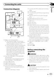
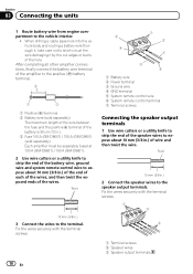
...and the positive + terminal of the battery. 2 Fuse 100 A (GM-D8601) / 150 A (GM-D9601) (sold separately) Each amplifier must be separately fused at the amplifier, connect the battery wire terminal of the amplifier to the positive + terminal of the battery is limited. Connect to ... switch. For the wire size, refer to other connections at 100 A (GM-D8601) / 150 A (GM-D9601). 3 Positive (+) terminal 4 Negative (*) terminal 5 Battery (sold separately) 6 Ground wire, Terminal (sold se- parately) a Amplifier with cable clamps or adhe- g Speaker output terminals Please see the following ...
...and the positive + terminal of the battery. 2 Fuse 100 A (GM-D8601) / 150 A (GM-D9601) (sold separately) Each amplifier must be separately fused at the amplifier, connect the battery wire terminal of the amplifier to the positive + terminal of the battery is limited. Connect to ... switch. For the wire size, refer to other connections at 100 A (GM-D8601) / 150 A (GM-D9601). 3 Positive (+) terminal 4 Negative (*) terminal 5 Battery (sold separately) 6 Ground wire, Terminal (sold se- parately) a Amplifier with cable clamps or adhe- g Speaker output terminals Please see the following ...
Owner's Manual
Page 8
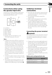
... two speakers is the same as possible from the speaker wires. When connecting to the power terminal via the ignition switch (12 V DC), the amplifier will remain on with the synthetic impedance less than 1 W, as possible from the antenna, antenna cable and tuner. Speaker output 8 En Section 03...parallel with the ignition whether the car stereo is canceled. Install and route the separately sold battery wire, ground wire, speaker wires and the amplifier as far away as that the synthetic impedance is at rest or idling. ! If the system remote control wire of one speaker Speaker ...
... two speakers is the same as possible from the speaker wires. When connecting to the power terminal via the ignition switch (12 V DC), the amplifier will remain on with the synthetic impedance less than 1 W, as possible from the antenna, antenna cable and tuner. Speaker output 8 En Section 03...parallel with the ignition whether the car stereo is canceled. Install and route the separately sold battery wire, ground wire, speaker wires and the amplifier as far away as that the synthetic impedance is at rest or idling. ! If the system remote control wire of one speaker Speaker ...
Owner's Manual
Page 9
...sold separately. Connecting the units Section 03 English Connections when using the speaker input wire Connect the car stereo speaker output wires to the amplifier using the terminal screws, there is as necessary. ! In such cases, please use it must be same size. ! Connecting the...and the ground wire to be periodically inspected and tightened as follows. Use a wire of this screw, which is turned off, the amplifier turns off automatically. The battery wire, the ground wire and the optional direct ground wire must be connected together synchronously, connect the ...
...sold separately. Connecting the units Section 03 English Connections when using the speaker input wire Connect the car stereo speaker output wires to the amplifier using the terminal screws, there is as necessary. ! In such cases, please use it must be same size. ! Connecting the...and the ground wire to be periodically inspected and tightened as follows. Use a wire of this screw, which is turned off, the amplifier turns off automatically. The battery wire, the ground wire and the optional direct ground wire must be connected together synchronously, connect the ...
Owner's Manual
Page 10
... the wire between the fuse and the positive + terminal of the battery is 30 cm (12 in.). 3 Fuse 100 A (GM-D8601) / 150 A (GM-D9601) (sold separately) Each amplifier must be separately fused at 100 A (GM-D8601) / 150 A (GM-D9601). 2 Use wire cutters or a utility knife to strip the end of the battery wire, ground wire and system...
... the wire between the fuse and the positive + terminal of the battery is 30 cm (12 in.). 3 Fuse 100 A (GM-D8601) / 150 A (GM-D9601) (sold separately) Each amplifier must be separately fused at 100 A (GM-D8601) / 150 A (GM-D9601). 2 Use wire cutters or a utility knife to strip the end of the battery wire, ground wire and system...
Owner's Manual
Page 11
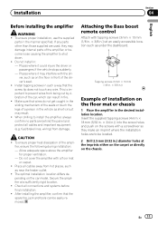
...where it could injure the driver or passengers if the vehicle stops suddenly. - Install tapping screws in the manner specified. Allow adequate space above the amplifier for proper ventilation. - Places where it may interfere with tapping screws (3 mm × 10 mm (1/8 in. × 3/8 in the ... ! fuel/brake lines, wiring) from hot places, such as short-circuit may damage internal parts of the driver's seat. ! Secure the amplifier at the imprints either on the carpet or directly on the chassis. To ensure proper heat dissipation of a person in .)) at an easily ...
...where it could injure the driver or passengers if the vehicle stops suddenly. - Install tapping screws in the manner specified. Allow adequate space above the amplifier for proper ventilation. - Places where it may interfere with tapping screws (3 mm × 10 mm (1/8 in. × 3/8 in the ... ! fuel/brake lines, wiring) from hot places, such as short-circuit may damage internal parts of the driver's seat. ! Secure the amplifier at the imprints either on the carpet or directly on the chassis. To ensure proper heat dissipation of a person in .)) at an easily ...
Owner's Manual
Page 12
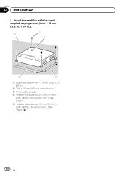
Section 04 Installation 3 Install the amplifier with the use of supplied tapping screws (4 mm × 18 mm ( 5/32 in. × 3/4 in.)). 1 3 2 4 5 1 Tapping-screws (4 mm × 18 mm (5/32 in. × 3/4 in.)) 2 Drill a 2.5 mm (3/32 in.) diameter hole. 3 Floor mat or chassis 4 Hole-to-hole distance: 257 mm (10-1/8 in.) (GM-D8601) / 307 mm (12-1/8 in.) (GMD9601) 5 Hole-to-hole distance: 181 mm (7-1/8 in.) (GM-D8601) / 181 mm (7-1/8 in.) (GMD9601) 12 En
Section 04 Installation 3 Install the amplifier with the use of supplied tapping screws (4 mm × 18 mm ( 5/32 in. × 3/4 in.)). 1 3 2 4 5 1 Tapping-screws (4 mm × 18 mm (5/32 in. × 3/4 in.)) 2 Drill a 2.5 mm (3/32 in.) diameter hole. 3 Floor mat or chassis 4 Hole-to-hole distance: 257 mm (10-1/8 in.) (GM-D8601) / 307 mm (12-1/8 in.) (GMD9601) 5 Hole-to-hole distance: 181 mm (7-1/8 in.) (GM-D8601) / 181 mm (7-1/8 in.) (GMD9601) 12 En
Owner's Manual
Page 14
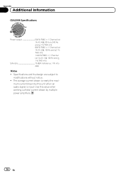
... (at 14.4 V, 1 W, 100 Hz and ≦ 1 % THD+N) S/N ratio 75 dBA (reference: 1 W into 4 W) Notes ! The average current drawn is input. mum current drawn by multiple power amplifiers. 14 En Use this value when working out total current drawn by this unit when an audio signal is nearly the maxi- Appendix Additional information...
... (at 14.4 V, 1 W, 100 Hz and ≦ 1 % THD+N) S/N ratio 75 dBA (reference: 1 W into 4 W) Notes ! The average current drawn is input. mum current drawn by multiple power amplifiers. 14 En Use this value when working out total current drawn by this unit when an audio signal is nearly the maxi- Appendix Additional information...

