Owner's Manual
Page 2
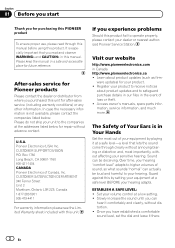
... product updates (such as firm- Set your dealer or nearest authorized Pioneer Service Station. The Safety of Canada, Inc. Guard against this manual. Please keep the manual in Your Hands Get the most importantly, without distortion. ! After-sales service for Pioneer products Please contact the dealer or distributor from where you purchased this unit for purchasing this PIONEER product To ensure proper use...
... product updates (such as firm- Set your dealer or nearest authorized Pioneer Service Station. The Safety of Canada, Inc. Guard against this manual. Please keep the manual in Your Hands Get the most importantly, without distortion. ! After-sales service for Pioneer products Please contact the dealer or distributor from where you purchased this unit for purchasing this PIONEER product To ensure proper use...
Owner's Manual
Page 3
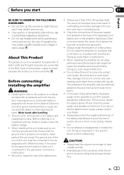
... battery wire. ! Do not use of this product is illegal in malfunction. ! The ground wire of the one of headphones may also heat up the volume so high that the ground wire is cut off and check the power supply and speaker connections. Determine and resolve the cause, then replace the fuse with different screws. gine is for subwoofer. the use headphones while operating a motorized vehicle; When installing this unit...
... battery wire. ! Do not use of this product is illegal in malfunction. ! The ground wire of the one of headphones may also heat up the volume so high that the ground wire is cut off and check the power supply and speaker connections. Determine and resolve the cause, then replace the fuse with different screws. gine is for subwoofer. the use headphones while operating a motorized vehicle; When installing this unit...
Owner's Manual
Page 4
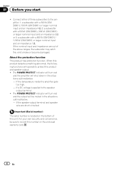
... nominal input and impedance are short-circuited. The POWER/PROTECT indicator will turn red and the amplifier will shut down in the situations outlined below . - About the protection function This product has protection function. If the speaker output terminal and speaker wire are out of this unit. When this number on the bottom of the above ranges, the subwoofer may catch fire, emit smoke or become damaged. Connect either of three subwoofers to...
... nominal input and impedance are short-circuited. The POWER/PROTECT indicator will turn red and the amplifier will shut down in the situations outlined below . - About the protection function This product has protection function. If the speaker output terminal and speaker wire are out of this unit. When this number on the bottom of the above ranges, the subwoofer may catch fire, emit smoke or become damaged. Connect either of three subwoofers to...
Owner's Manual
Page 5
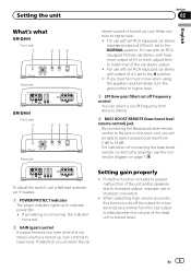
... the unit and/or speakers due to excessive output, improper use with an RCA equipped car stereo (standard output of 500 mV), set to the H position. ! En 5 For use or improper connection. ! To adjust the switch, use a flathead screwdriver if needed. 1 POWER/PROTECT indicator The power indicator lights up , turn controls to lower level. If you hear too much noise when using the speaker input terminals, turn the gain control to higher level. 3 LPF (low-pass filter) cut off frequency control You can select a cut off the output for...
... the unit and/or speakers due to excessive output, improper use with an RCA equipped car stereo (standard output of 500 mV), set to the H position. ! En 5 For use or improper connection. ! To adjust the switch, use a flathead screwdriver if needed. 1 POWER/PROTECT indicator The power indicator lights up , turn controls to lower level. If you hear too much noise when using the speaker input terminals, turn the gain control to higher level. 3 LPF (low-pass filter) cut off frequency control You can select a cut off the output for...
Owner's Manual
Page 6
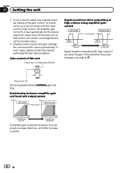
... increase in sound output may indicate improper setting of the gain control. Relationship between amplifier gain and head unit output power If amplifier gain is raised improperly, this unit Preout level: 2 V (Standard: 500 mV) Signal waveform when outputting at high volume using amplifier gain control Signal waveform distorted with the head unit at a high volume, set amplifier gain control to a level appropriate for the preout maximum output level of the amplifier the power changes only slightly. In such cases, please contact the nearest authorized Pioneer Service Station. Preout...
... increase in sound output may indicate improper setting of the gain control. Relationship between amplifier gain and head unit output power If amplifier gain is raised improperly, this unit Preout level: 2 V (Standard: 500 mV) Signal waveform when outputting at high volume using amplifier gain control Signal waveform distorted with the head unit at a high volume, set amplifier gain control to a level appropriate for the preout maximum output level of the amplifier the power changes only slightly. In such cases, please contact the nearest authorized Pioneer Service Station. Preout...
Owner's Manual
Page 7
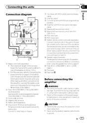
... tape. Current capacity of the amplifier to Connections when using the speaker input wire on page 9. CAUTION ! En 7 After making all other equipment. If the car stereo lacks a system remote control terminal, connect the male terminal to ground. Secure the wiring with RCA pin plugs (sold separately) The ground wires must be same size. Never wire the speaker negative cable directly- g Speaker output terminals Please see the following section for speaker connection instructions. rately) b Bass boost level remote control c Bass boost level remote control wire (5 m (16 ft. 5 in...
... tape. Current capacity of the amplifier to Connections when using the speaker input wire on page 9. CAUTION ! En 7 After making all other equipment. If the car stereo lacks a system remote control terminal, connect the male terminal to ground. Secure the wiring with RCA pin plugs (sold separately) The ground wires must be same size. Never wire the speaker negative cable directly- g Speaker output terminals Please see the following section for speaker connection instructions. rately) b Bass boost level remote control c Bass boost level remote control wire (5 m (16 ft. 5 in...
Owner's Manual
Page 8
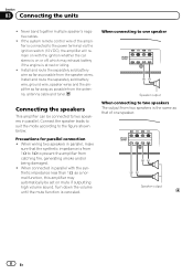
... remote control wire of one speaker Speaker output When connecting to the power terminal via the ignition switch (12 V DC), the amplifier will remain on mute if outputting high volume sound. Connecting the speakers This amplifier can be set on with the synthetic impedance less than 1 W, as a normal function, this amplifier may exhaust battery if the engine is connected to two speakers The output from the antenna, antenna cable and tuner. When wiring two speakers in parallel. Speaker output 8 En Install...
... remote control wire of one speaker Speaker output When connecting to the power terminal via the ignition switch (12 V DC), the amplifier will remain on mute if outputting high volume sound. Connecting the speakers This amplifier can be set on with the synthetic impedance less than 1 W, as a normal function, this amplifier may exhaust battery if the engine is connected to two speakers The output from the antenna, antenna cable and tuner. When wiring two speakers in parallel. Speaker output 8 En Install...
Owner's Manual
Page 9
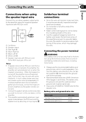
... the twisted wires. ! If multiple amplifiers are connected to be connected together synchronously, connect the head unit and all amplifiers via the system remote control wire. ! Solderless terminal connections ! Always use the recommended battery and ground wire, which is not securely fixed to the terminal using the supplied speaker input wire with RCA pin cord. 1 Car Stereo 2 Speaker output 3 Red: Right + 4 Black: Right * 5 Black: Left * 6 White: Left + 7 Speaker input wire with an RCA pin cord from a headunit are to this screw, which may not work with some...
... the twisted wires. ! If multiple amplifiers are connected to be connected together synchronously, connect the head unit and all amplifiers via the system remote control wire. ! Solderless terminal connections ! Always use the recommended battery and ground wire, which is not securely fixed to the terminal using the supplied speaker input wire with RCA pin cord. 1 Car Stereo 2 Speaker output 3 Red: Right + 4 Black: Right * 5 Black: Left * 6 White: Left + 7 Speaker input wire with an RCA pin cord from a headunit are to this screw, which may not work with some...
Owner's Manual
Page 10
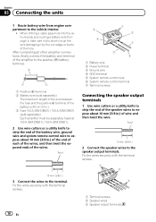
... 3 Fuse 100 A (GM-D8601) / 150 A (GM-D9601) (sold separately) Each amplifier must be separately fused at 100 A (GM-D8601) / 150 A (GM-D9601). 2 Use wire cutters or a utility knife to strip the end of the battery wire, ground wire and system remote control wire to expose about 10 mm (3/8 in .) of wire and then twist the wire. Fix the wires securely with the terminal screws. 6 4 7 2 1 3 5 1 Battery wire 2 Power terminal 3 Ground wire 4 GND terminal 5 System remote control wire 6 System remote control terminal 7 Terminal screws Connecting the speaker output terminals 1 Use wire cutters...
... 3 Fuse 100 A (GM-D8601) / 150 A (GM-D9601) (sold separately) Each amplifier must be separately fused at 100 A (GM-D8601) / 150 A (GM-D9601). 2 Use wire cutters or a utility knife to strip the end of the battery wire, ground wire and system remote control wire to expose about 10 mm (3/8 in .) of wire and then twist the wire. Fix the wires securely with the terminal screws. 6 4 7 2 1 3 5 1 Battery wire 2 Power terminal 3 Ground wire 4 GND terminal 5 System remote control wire 6 System remote control terminal 7 Terminal screws Connecting the speaker output terminals 1 Use wire cutters...
Owner's Manual
Page 11
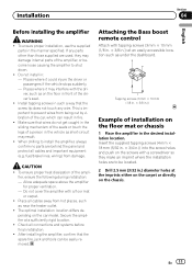
... parts other than those supplied are to prevent wires from hot places, such as under the dashboard. Place all cables away from being cut by vibration of a person in : - Attaching the Bass boost remote control Attach with a screwdriver so they make an imprint where the installation holes are used, they may result. ! CAUTION ! Installation Section 04 English Before installing the amplifier WARNING ! Do not install...
... parts other than those supplied are to prevent wires from hot places, such as under the dashboard. Place all cables away from being cut by vibration of a person in : - Attaching the Bass boost remote control Attach with a screwdriver so they make an imprint where the installation holes are used, they may result. ! CAUTION ! Installation Section 04 English Before installing the amplifier WARNING ! Do not install...
Owner's Manual
Page 12
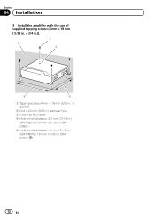
Section 04 Installation 3 Install the amplifier with the use of supplied tapping screws (4 mm × 18 mm ( 5/32 in. × 3/4 in.)). 1 3 2 4 5 1 Tapping-screws (4 mm × 18 mm (5/32 in. × 3/4 in.)) 2 Drill a 2.5 mm (3/32 in.) diameter hole. 3 Floor mat or chassis 4 Hole-to-hole distance: 257 mm (10-1/8 in.) (GM-D8601) / 307 mm (12-1/8 in.) (GMD9601) 5 Hole-to-hole distance: 181 mm (7-1/8 in.) (GM-D8601) / 181 mm (7-1/8 in.) (GMD9601) 12 En
Section 04 Installation 3 Install the amplifier with the use of supplied tapping screws (4 mm × 18 mm ( 5/32 in. × 3/4 in.)). 1 3 2 4 5 1 Tapping-screws (4 mm × 18 mm (5/32 in. × 3/4 in.)) 2 Drill a 2.5 mm (3/32 in.) diameter hole. 3 Floor mat or chassis 4 Hole-to-hole distance: 257 mm (10-1/8 in.) (GM-D8601) / 307 mm (12-1/8 in.) (GMD9601) 5 Hole-to-hole distance: 181 mm (7-1/8 in.) (GM-D8601) / 181 mm (7-1/8 in.) (GMD9601) 12 En
Owner's Manual
Page 13
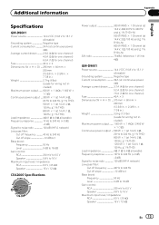
...-to-noise ratio 100 dB (IHF-A network) Low pass filter: Cut off frequency 40 Hz to 240 Hz Cut off slope 12 dB/oct Bass boost: Frequency 50 Hz Level 0 dB to 18 dB Gain control: RCA 200 mV to 6.5 V Speaker 0.8 V to 16 V Maximum input level / impedance: RCA 6.5 V / 25 kW Speaker 16 V / 12 kW CEA2006 Specifications Power output 300 W RMS × 1 Channel (at 14.4 V, 4 W, 20 Hz to 240 Hz and...
...-to-noise ratio 100 dB (IHF-A network) Low pass filter: Cut off frequency 40 Hz to 240 Hz Cut off slope 12 dB/oct Bass boost: Frequency 50 Hz Level 0 dB to 18 dB Gain control: RCA 200 mV to 6.5 V Speaker 0.8 V to 16 V Maximum input level / impedance: RCA 6.5 V / 25 kW Speaker 16 V / 12 kW CEA2006 Specifications Power output 300 W RMS × 1 Channel (at 14.4 V, 4 W, 20 Hz to 240 Hz and...
Owner's Manual
Page 14
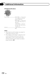
Use this value when working out total current drawn by this unit when an audio signal is nearly the maxi- mum current drawn by multiple power amplifiers. 14 En Appendix Additional information CEA2006 Specifications Power output 500 W RMS × 1 Channel (at 14.4 V, 4 W, 20 Hz to modifications without notice. ! The average current drawn is input. Specifications and the design are subject to 240 Hz...
Use this value when working out total current drawn by this unit when an audio signal is nearly the maxi- mum current drawn by multiple power amplifiers. 14 En Appendix Additional information CEA2006 Specifications Power output 500 W RMS × 1 Channel (at 14.4 V, 4 W, 20 Hz to modifications without notice. ! The average current drawn is input. Specifications and the design are subject to 240 Hz...
Owner's Manual
Page 44
...Col.Lomas de Chapultepec, Mexico, D.F. 11000 TEL: 55-9178-4270 407號8 886-(0)2-2657-3588 909號5 852-2848-6488 ã 2012 PIONEER CORPORATION. Tous droits de reproduction et de traduction réservés. Printed in China Imprimé en Chine UC de C.V. P.O. All rights... reserved. ã 2012 PIONEER CORPORATION. LTD. 5 Arco Lane, Heatherton, Victoria, 3202 Australia TEL: (03) 9586-6300 PIONEER ELECTRONICS OF CANADA, INC. 340 Ferrier Street, Unit 2, Markham, Ontario L3R 2Z5, Canada TEL: 1-877-283-5901 TEL: 905-479-...
...Col.Lomas de Chapultepec, Mexico, D.F. 11000 TEL: 55-9178-4270 407號8 886-(0)2-2657-3588 909號5 852-2848-6488 ã 2012 PIONEER CORPORATION. Tous droits de reproduction et de traduction réservés. Printed in China Imprimé en Chine UC de C.V. P.O. All rights... reserved. ã 2012 PIONEER CORPORATION. LTD. 5 Arco Lane, Heatherton, Victoria, 3202 Australia TEL: (03) 9586-6300 PIONEER ELECTRONICS OF CANADA, INC. 340 Ferrier Street, Unit 2, Markham, Ontario L3R 2Z5, Canada TEL: 1-877-283-5901 TEL: 905-479-...


