Owner's Manual
Page 2
... Unit 3 Gain Control 3 LPF (Low-Pass-Filter) Cut Off Frequency Control 4 Power Indicator (Blue 4 Input Switch 4 Bass Boost Control 4 Setting the Gain properly 5 Connecting the Unit 6 Connection Diagram 7 Solderless Terminal Connections 8 Connecting the Power Terminal 8 Connecting the Speaker Output Terminals ...... 9 Using the Speaker Input 9 Connecting the Speaker Wires 9 Installation 10 Attaching the Bass boost remote control ........ 11 Example of installation on the floor mat or on the chassis 11 Specifications 12 Thank you purchased the product for its aftersales service...
... Unit 3 Gain Control 3 LPF (Low-Pass-Filter) Cut Off Frequency Control 4 Power Indicator (Blue 4 Input Switch 4 Bass Boost Control 4 Setting the Gain properly 5 Connecting the Unit 6 Connection Diagram 7 Solderless Terminal Connections 8 Connecting the Power Terminal 8 Connecting the Speaker Output Terminals ...... 9 Using the Speaker Input 9 Connecting the Speaker Wires 9 Installation 10 Attaching the Bass boost remote control ........ 11 Example of installation on the floor mat or on the chassis 11 Specifications 12 Thank you purchased the product for its aftersales service...
Owner's Manual
Page 3
... of the power supply and subwoofer. Connect the battery wire directly to the car battery positive terminal (+) and the ground wire to , for the subwoofer. Otherwise you use of the unit. About This Product This product is a class D amplifier for example, the location where the amplifier is installed. Use of the separately sold separately. Also, do not touch the amplifier when it down on the latest products and technologies. 3 Download owner's manuals, order...
... of the power supply and subwoofer. Connect the battery wire directly to the car battery positive terminal (+) and the ground wire to , for the subwoofer. Otherwise you use of the unit. About This Product This product is a class D amplifier for example, the location where the amplifier is installed. Use of the separately sold separately. Also, do not touch the amplifier when it down on the latest products and technologies. 3 Download owner's manuals, order...
Owner's Manual
Page 4
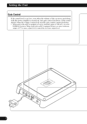
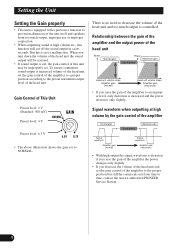
output of 500 mV), set to match the car stereo output level. 3 If the sound distorts when the volume is turned up , turn gain control clockwise. Setting the Unit Gain Control If the sound level is too low, even when the volume of the car stereo used along with this power amplifier is turned up , turn the gain control counterclockwise. • When using with an RCA equipped Pioneer car stereo with an RCA equipped car stereo (standard output of 4 V or more, adjust level to the NORMAL position. When using with max.
output of 500 mV), set to match the car stereo output level. 3 If the sound distorts when the volume is turned up , turn gain control clockwise. Setting the Unit Gain Control If the sound level is too low, even when the volume of the car stereo used along with this power amplifier is turned up , turn the gain control counterclockwise. • When using with an RCA equipped Pioneer car stereo with an RCA equipped car stereo (standard output of 4 V or more, adjust level to the NORMAL position. When using with max.
Owner's Manual
Page 5
...-Pass-Filter) Cut Off Frequency Control You can select a cut off by a protection function. Switch the input switch before turning on . For instruction of connecting the bass boost remote control to use the supplied speaker input wire with RCA pin cord. Power Indicator (Blue) The power indicator lights when the power is turned off frequency from 0 dB to the left (SP). For details, see the "Connection Diagram" section. Bass Boost Control You can cause a loud noise to 240 Hz. Since switching the input switch while the power is on can adjust a bass boost level...
...-Pass-Filter) Cut Off Frequency Control You can select a cut off by a protection function. Switch the input switch before turning on . For instruction of connecting the bass boost remote control to use the supplied speaker input wire with RCA pin cord. Power Indicator (Blue) The power indicator lights when the power is turned off frequency from 0 dB to the left (SP). For details, see the "Connection Diagram" section. Bass Boost Control You can cause a loud noise to 240 Hz. Since switching the input switch while the power is on can adjust a bass boost level...
Owner's Manual
Page 6
... improper level, only distortion is controlled. Relationship between the gain of the amplifier and the output power of the head unit Power Normal gain Power Maximum gain Equal power Head unit volume steps Amplifier gain (normal) Head unit volume steps Amplifier gain (maximum) • If you turn down the volume of the head unit the sound output will cut , the gain control of this is not a malfunction. Setting the Unit Setting the Gain properly • This unit is equipped with a protective function to prevent malfunction of the unit itself and speakers...
... improper level, only distortion is controlled. Relationship between the gain of the amplifier and the output power of the head unit Power Normal gain Power Maximum gain Equal power Head unit volume steps Amplifier gain (normal) Head unit volume steps Amplifier gain (maximum) • If you turn down the volume of the head unit the sound output will cut , the gain control of this is not a malfunction. Setting the Unit Setting the Gain properly • This unit is equipped with a protective function to prevent malfunction of the unit itself and speakers...
Owner's Manual
Page 7
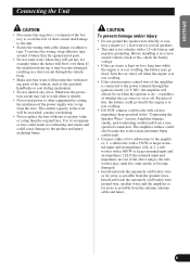
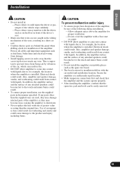
... separately sold battery wire as far away as possible from a nonspecified connection. CAUTION: To prevent damage and/or injury • Do not ground the speaker wire directly or connect a negative (-) lead wire for several speakers. • This unit is connected to the amplifier; 1: a subwoofer with a 350 W or larger nominal input and an impedance 4 Ω, or 2: a subwoofer with a lower impedance than the original fuse. Turn the car stereo off . Amplifier damage, smoke...
... separately sold battery wire as far away as possible from a nonspecified connection. CAUTION: To prevent damage and/or injury • Do not ground the speaker wire directly or connect a negative (-) lead wire for several speakers. • This unit is connected to the amplifier; 1: a subwoofer with a 350 W or larger nominal input and an impedance 4 Ω, or 2: a subwoofer with a lower impedance than the original fuse. Turn the car stereo off . Amplifier damage, smoke...
Owner's Manual
Page 8
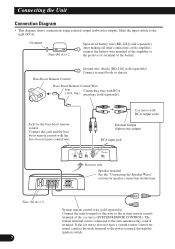
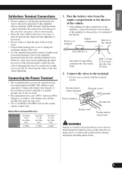
... Boost Remote Control Ground wire (black) [RD-228] (sold separately). Grommet Fuse (40 A) × 2 Special red battery wire [RD-228] (sold separately) Connect the male terminal of this jack and the bass boost remote control with the bass boost remote control wire. Jack for speaker connection instructions. Fuse (30 A) × 2 7 System remote control wire (sold separately) After making all other connections at the amplifier, connect the battery wire terminal of the amplifier to metal body or chassis. If the car stereo does not have a system remote control terminal, connect...
... Boost Remote Control Ground wire (black) [RD-228] (sold separately). Grommet Fuse (40 A) × 2 Special red battery wire [RD-228] (sold separately) Connect the male terminal of this jack and the bass boost remote control with the bass boost remote control wire. Jack for speaker connection instructions. Fuse (30 A) × 2 7 System remote control wire (sold separately) After making all other connections at the amplifier, connect the battery wire terminal of the amplifier to metal body or chassis. If the car stereo does not have a system remote control terminal, connect...
Owner's Manual
Page 9
... the terminal screw of the wire. • Use the supplied hexagonal wrench to 20 AWG wire for the system remote control wire. Pass the battery wire from the engine compartment to the interior of the vehicle. • After making sure to not to clamp the insulating sheath of the amplifier. Connect the battery wire directly to the car battery positive terminal (+) and the ground wire to the power terminals of the vehicle Fuse (40...
... the terminal screw of the wire. • Use the supplied hexagonal wrench to 20 AWG wire for the system remote control wire. Pass the battery wire from the engine compartment to the interior of the vehicle. • After making sure to not to clamp the insulating sheath of the amplifier. Connect the battery wire directly to the car battery positive terminal (+) and the ground wire to the power terminals of the vehicle Fuse (40...
Owner's Manual
Page 10
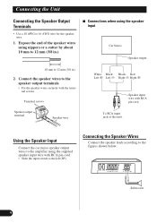
... left (SP). Subwoofer 9 Expose the end of this unit. Terminal screws Speaker output terminal Speaker wire White: Black: Black: Red: Left + Left ≠ Right ≠ Right + Speaker input wire with the terminal screws. Connecting the Speaker Wires Connect the speaker leads according to 16 AWG wire for the speaker wire. 1. Connecting the Unit Connecting the Speaker Output Terminals • Use a 10 AWG to the figures shown below. Using the Speaker Input Connect the car stereo speaker output wires to the amplifier using the speaker input Car Stereo Speaker output 10 mm...
... left (SP). Subwoofer 9 Expose the end of this unit. Terminal screws Speaker output terminal Speaker wire White: Black: Black: Red: Left + Left ≠ Right ≠ Right + Speaker input wire with the terminal screws. Connecting the Speaker Wires Connect the speaker leads according to 16 AWG wire for the speaker wire. 1. Connecting the Unit Connecting the Speaker Output Terminals • Use a 10 AWG to the figures shown below. Using the Speaker Input Connect the car stereo speaker output wires to the amplifier using the speaker input Car Stereo Speaker output 10 mm...
Owner's Manual
Page 11
...; Make sure that wires are not caught in the sliding mechanism of the seats, resulting in a short-circuit. • Confirm that no parts are used, they may damage internal parts of the amplifier, or they may interfere with the driver, such as on unstable places such as fuel lines, brake lines and electrical wiring from being cut by vibration of the car, which...
...; Make sure that wires are not caught in the sliding mechanism of the seats, resulting in a short-circuit. • Confirm that no parts are used, they may damage internal parts of the amplifier, or they may interfere with the driver, such as on unstable places such as fuel lines, brake lines and electrical wiring from being cut by vibration of the car, which...
Owner's Manual
Page 12
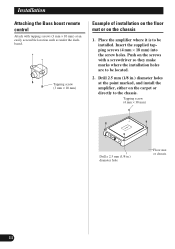
... Floor mat or chassis 11 Place the amplifier where it is to be installed. Installation Attaching the Bass boost remote control Attach with a screwdriver so they make marks where the installation holes are to be located. 2. Tapping screw (3 mm × 10 mm) Example of installation on the floor mat or on the carpet or directly to the chassis. Insert the supplied tapping...
... Floor mat or chassis 11 Place the amplifier where it is to be installed. Installation Attaching the Bass boost remote control Attach with a screwdriver so they make marks where the installation holes are to be located. 2. Tapping screw (3 mm × 10 mm) Example of installation on the floor mat or on the carpet or directly to the chassis. Insert the supplied tapping...
Owner's Manual
Page 13
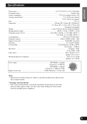
...) Distortion ...0.3 % (10 W, 100 Hz) Low pass filter ...Cut off frequency: 40 Hz to 240 Hz Cut off slope: -12 dB/oct Bass Boost ...Frequency: 50 Hz Level: 0 dB to 12 dB Gain control ...RCA: 200 mV to 6.5 V Speaker: 0.8 V to 26 V Maximum input level / impedance ...RCA: 6.5 V / 22 kΩ Speaker: 26 V / 90 kΩ Power output 300 W RMS × 1 channel (4 Ω and 1 % THD+N) 600 W RMS × 1 channel (2 Ω and 1 % THD+N, 50 Hz) Signal...
...) Distortion ...0.3 % (10 W, 100 Hz) Low pass filter ...Cut off frequency: 40 Hz to 240 Hz Cut off slope: -12 dB/oct Bass Boost ...Frequency: 50 Hz Level: 0 dB to 12 dB Gain control ...RCA: 200 mV to 6.5 V Speaker: 0.8 V to 26 V Maximum input level / impedance ...RCA: 6.5 V / 22 kΩ Speaker: 26 V / 90 kΩ Power output 300 W RMS × 1 channel (4 Ω and 1 % THD+N) 600 W RMS × 1 channel (2 Ω and 1 % THD+N, 50 Hz) Signal...


