
Owners Manual
Page 5
...wire of the one of the rating prescribed. Always use of any attached speakers may also heat up and cause minor burns. ! When installing the amplifier, do not allow this unit, smoke, and overheating could result in fire, generation of the car stereo while the en- Always disconnect the negative ... so could result in overheating and smoke, damage to avoid the risk of the car's body. Do not attempt to get caught between the amplifier and the automobile. Ensure that is at rest or idling may result in moderate and tro- If you start Before connecting/ installing the...
...wire of the one of the rating prescribed. Always use of any attached speakers may also heat up and cause minor burns. ! When installing the amplifier, do not allow this unit, smoke, and overheating could result in fire, generation of the car stereo while the en- Always disconnect the negative ... so could result in overheating and smoke, damage to avoid the risk of the car's body. Do not attempt to get caught between the amplifier and the automobile. Ensure that is at rest or idling may result in moderate and tro- If you start Before connecting/ installing the...
Owners Manual
Page 6
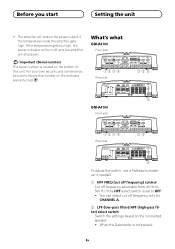
... HPF select switch is connected: En When the Subwoofer is set to HPF. ! Before you start Setting the unit ! The amplifier will shut down. What's what GM-A6704 Front side Rear side GM-A4704 Front side Rear side To adjust the switch, use a flathead screwdriver if needed. 1 HPF FREQ (cut off frequency only for... power indicator will turn off frequency selectable from 40 Hz to record this unit. You can select cut off frequency) control Cut off , and the amplifier will reduce the power output if the temperature inside the...
... HPF select switch is connected: En When the Subwoofer is set to HPF. ! Before you start Setting the unit ! The amplifier will shut down. What's what GM-A6704 Front side Rear side GM-A4704 Front side Rear side To adjust the switch, use a flathead screwdriver if needed. 1 HPF FREQ (cut off frequency only for... power indicator will turn off frequency selectable from 40 Hz to record this unit. You can select cut off frequency) control Cut off , and the amplifier will reduce the power output if the temperature inside the...

Owners Manual
Page 7
...as a normal function, but output is turned up, turn the controls to the NORMAL position. For use with output of 4 V, set amplifier gain control to a level appropriate for the preout maximum output level of the head unit, so that of 4 V or more, adjust level.... Bass boost level setting applies only to CHANNEL B (channel B) output. 6 Power indicator The power indicator lights up , turn these controls to the Pioneer amplifier. For connections when using the RCA input jack. When outputting high volume sound etc., this unit Preout level: 2 V (Standard: 500 mV) Preout level...
...as a normal function, but output is turned up, turn the controls to the NORMAL position. For use with output of 4 V, set amplifier gain control to a level appropriate for the preout maximum output level of the head unit, so that of 4 V or more, adjust level.... Bass boost level setting applies only to CHANNEL B (channel B) output. 6 Power indicator The power indicator lights up , turn these controls to the Pioneer amplifier. For connections when using the RCA input jack. When outputting high volume sound etc., this unit Preout level: 2 V (Standard: 500 mV) Preout level...

Owners Manual
Page 8
...output power will change only slightly. 1 Special red battery wire RD-223 (sold separately) After completing all other amplifier connections, finally connect the battery wire terminal of the amplifier to the positive + battery terminal. 2 Ground wire (Black) RD-223 (sold separately) 6 RCA input jack ...Speaker input terminal (use a connector in power. cluded) En Setting the unit Connecting the units Relationship between amplifier gain and head unit output power Connection diagram If amplifier gain is used, do not connect anything to metal body or chassis. 3 Car stereo with RCA output ...
...output power will change only slightly. 1 Special red battery wire RD-223 (sold separately) After completing all other amplifier connections, finally connect the battery wire terminal of the amplifier to the positive + battery terminal. 2 Ground wire (Black) RD-223 (sold separately) 6 RCA input jack ...Speaker input terminal (use a connector in power. cluded) En Setting the unit Connecting the units Relationship between amplifier gain and head unit output power Connection diagram If amplifier gain is used, do not connect anything to metal body or chassis. 3 Car stereo with RCA output ...

Owners Manual
Page 9
.... In addition, refer to achieve a 2 W (or lower) bridged mode (Diagram B). Never shorten any further enquiries, contact your local authorized Pioneer dealer or customer service. tive cables. ! To properly install or use a single 4 W speaker. For details, see the following section for information... to the touch and minor burns could result from the speaker wires. The amplifier surface could also become hot to the power terminal via the ignition switch. Refer to the auto-antenna relay control terminal. b Fuse 25 A × 2 (GM-A6704) / 30 A × 1 (GMA4704) c Fuse (30 A) ×...
.... In addition, refer to achieve a 2 W (or lower) bridged mode (Diagram B). Never shorten any further enquiries, contact your local authorized Pioneer dealer or customer service. tive cables. ! To properly install or use a single 4 W speaker. For details, see the following section for information... to the touch and minor burns could result from the speaker wires. The amplifier surface could also become hot to the power terminal via the ignition switch. Refer to the auto-antenna relay control terminal. b Fuse 25 A × 2 (GM-A6704) / 30 A × 1 (GMA4704) c Fuse (30 A) ×...

Owners Manual
Page 11
Connecting the units Three-channel output 1 3 2 Two-channel output (Mono) 4 1 Right 2 Left 3 Speaker out A 4 Speaker out B (Mono) Two-channel output (Stereo) 1 1 Speaker (Mono) Connections when using the RCA input jack Connect the car stereo RCA output jack and the RCA input jack of the amplifier. Slide INPUT SELECT (input select) switch to 4CH position. 12 1 Speaker (Right) 2 Speaker (Left) 2 3 4 1 RCA input jack A 2 RCA input jack B 3 Connecting wires with RCA plugs (sold sepa- rately) 4 From car stereo (RCA output) En Four-channel / Three-channel output !
Connecting the units Three-channel output 1 3 2 Two-channel output (Mono) 4 1 Right 2 Left 3 Speaker out A 4 Speaker out B (Mono) Two-channel output (Stereo) 1 1 Speaker (Mono) Connections when using the RCA input jack Connect the car stereo RCA output jack and the RCA input jack of the amplifier. Slide INPUT SELECT (input select) switch to 4CH position. 12 1 Speaker (Right) 2 Speaker (Left) 2 3 4 1 RCA input jack A 2 RCA input jack B 3 Connecting wires with RCA plugs (sold sepa- rately) 4 From car stereo (RCA output) En Four-channel / Three-channel output !

Owners Manual
Page 12
...Left * 8 Green: CH B, Left + 9 Violet/black: CH B, Right * a Violet: CH B, Right + b Speaker input connector To speaker input terminal of this amplifier, the amplifier will automatically turn on when the headunit is used, e.g. Two-channel output (Stereo) / (Mono) ! Note If speaker input wires from a headunit are to be connected... 3 From car stereo (RCA output) Connections when using the speaker input wire Connect the car stereo speaker output wires to the amplifier using the supplied speaker input wire. ! when the car stereo has only one input plug is turned on. Slide INPUT SELECT ...
...Left * 8 Green: CH B, Left + 9 Violet/black: CH B, Right * a Violet: CH B, Right + b Speaker input connector To speaker input terminal of this amplifier, the amplifier will automatically turn on when the headunit is used, e.g. Two-channel output (Stereo) / (Mono) ! Note If speaker input wires from a headunit are to be connected... 3 From car stereo (RCA output) Connections when using the speaker input wire Connect the car stereo speaker output wires to the amplifier using the supplied speaker input wire. ! when the car stereo has only one input plug is turned on. Slide INPUT SELECT ...

Owners Manual
Page 13
..., finally connect the battery wire terminal of the amplifier to short-circuit the wire damaging it , take care not to the positive + battery terminal. 2 Twist the battery wire, ground wire and system remote control ...
..., finally connect the battery wire terminal of the amplifier to short-circuit the wire damaging it , take care not to the positive + battery terminal. 2 Twist the battery wire, ground wire and system remote control ...

Owners Manual
Page 14
... use the supplied parts in : - If any wire. En Do not install in the manner specified. Allow adequate space above the amplifier for proper ventilation. - Protection function may result. ! The optimal installation location differs depending on the floor in front of a person in...(3/8 in.) of the car, which can result in fire. ! Places where it has cooled to prevent wires from damage. Secure the amplifier at a sufficiently rigid location. To ensure proper installation, use under high-volume conditions, etc. Install tapping screws in such a way that...
... use the supplied parts in : - If any wire. En Do not install in the manner specified. Allow adequate space above the amplifier for proper ventilation. - Protection function may result. ! The optimal installation location differs depending on the floor in front of a person in...(3/8 in.) of the car, which can result in fire. ! Places where it has cooled to prevent wires from damage. Secure the amplifier at a sufficiently rigid location. To ensure proper installation, use under high-volume conditions, etc. Install tapping screws in such a way that...

Owners Manual
Page 15
Check all connections and systems before final installation. ! A4704) 5 Hole-to-hole distance: 195 mm (7-5/8 in.) Specifications GM-A6704 Power source 14.4 V DC (10.8 V to 15.1 V allowable) Grounding system Negative type Current consumption 31 A (at 14.4 V, 2 W, 1 kHz, ≦ 1 % THD+N) Load impedance 4 W... be located. 2 Drill 2.5 mm (1/8 in.) diameter holes at the imprints either on the carpet or directly on the chassis. 3 Install the amplifier with the use of installation on the screws with a screwdriver so they make an imprint where the installation holes are to 20 kHz ≦ ...
Check all connections and systems before final installation. ! A4704) 5 Hole-to-hole distance: 195 mm (7-5/8 in.) Specifications GM-A6704 Power source 14.4 V DC (10.8 V to 15.1 V allowable) Grounding system Negative type Current consumption 31 A (at 14.4 V, 2 W, 1 kHz, ≦ 1 % THD+N) Load impedance 4 W... be located. 2 Drill 2.5 mm (1/8 in.) diameter holes at the imprints either on the carpet or directly on the chassis. 3 Install the amplifier with the use of installation on the screws with a screwdriver so they make an imprint where the installation holes are to 20 kHz ≦ ...

Owners Manual
Page 16
...Specifications Power output 60 W RMS × 4 Channels (at 14.4 V, 4 W and ≦ 1 % THD +N) S/N ratio 78 dBA (reference: 1 W into 4 W) GM-A4704 Power source 14.4 V DC (10.8 V to 15.1 V allowable) Grounding system Negative type Current consumption 20.5 A (at continuous power, 4 W) Average current consumption 5.5 A ...unit when an audio signal is nearly the maximum current consumption by this value when working out total current consumption by multiple power amplifiers. Specifications and the design are subject to 26 V Maximum input level / impedance: RCA 6.5 V / 22 kW Speaker 26...
...Specifications Power output 60 W RMS × 4 Channels (at 14.4 V, 4 W and ≦ 1 % THD +N) S/N ratio 78 dBA (reference: 1 W into 4 W) GM-A4704 Power source 14.4 V DC (10.8 V to 15.1 V allowable) Grounding system Negative type Current consumption 20.5 A (at continuous power, 4 W) Average current consumption 5.5 A ...unit when an audio signal is nearly the maximum current consumption by this value when working out total current consumption by multiple power amplifiers. Specifications and the design are subject to 26 V Maximum input level / impedance: RCA 6.5 V / 22 kW Speaker 26...

