Owner's Manual
Page 1
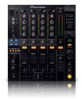
DJ MIXER DJM-800 Operating Instructions
DJ MIXER DJM-800 Operating Instructions
Owner's Manual
Page 2
...so you will not completely shut off and on a circuit different from the AC outlet in the cord or tie it damaged, ask your nearest PIONEER authorized service center or your model properly. When a cart is intended to alert the user to dripping, splashing, rain or moisture. Servicing is ... interference will need to shut down all servicing to which can radiate radio frequency energy and, if not installed and used , use this Pioneer product. D3-4-2-1-7b_A_En POWER-CORD CAUTION Handle the power cord by tugging the cord and never touch the power cord when your outlet, consult...
...so you will not completely shut off and on a circuit different from the AC outlet in the cord or tie it damaged, ask your nearest PIONEER authorized service center or your model properly. When a cart is intended to alert the user to dripping, splashing, rain or moisture. Servicing is ... interference will need to shut down all servicing to which can radiate radio frequency energy and, if not installed and used , use this Pioneer product. D3-4-2-1-7b_A_En POWER-CORD CAUTION Handle the power cord by tugging the cord and never touch the power cord when your outlet, consult...
Owner's Manual
Page 3
One that lets the sound come through loud and clear without annoying blaring or distortion-and, most out of your protection. Over time your new sound equipment will not be loud and harmful to excessive noise. Guard against this by playing it is too late, this manufacturer and the Electronic Industries Association's Consumer Electronics Group recommend you have established a comfortable sound level: • Set the dial and leave it will provide a lifetime of the sun, or near stoves or radiators. Excessive heat can actually be exposed to high temperatures or humidity. &#...
One that lets the sound come through loud and clear without annoying blaring or distortion-and, most out of your protection. Over time your new sound equipment will not be loud and harmful to excessive noise. Guard against this by playing it is too late, this manufacturer and the Electronic Industries Association's Consumer Electronics Group recommend you have established a comfortable sound level: • Set the dial and leave it will provide a lifetime of the sun, or near stoves or radiators. Excessive heat can actually be exposed to high temperatures or humidity. &#...
Owner's Manual
Page 4
...COLOR EFFECT 18 USING SOUND-COLOR EFFECTS 18 EFFECT PARAMETERS 19 MIDI SETTINGS 20 SYNCHRONIZING AUDIO SIGNALS TO EXTERNAL SEQUENCER, OR USING DJM-800 INFORMATION TO OPERATE AN EXTERNAL SEQUENCER 20 MIDI MESSAGES 20 PROGRAM CHANGE 21 SNAPSHOT 21 OTHER TROUBLESHOOTING 22 SPECIFICATIONS 23 BLOCK DIAGRAM ...so popular on other features of the high-fidelity technology also used to connect the unit to a Pioneer DJ CD player, thus allowing playback to be linked to operation of the DJM-800 can be output in the best possible state. Effects can be applied in each bandwidth. ¶ ...
...COLOR EFFECT 18 USING SOUND-COLOR EFFECTS 18 EFFECT PARAMETERS 19 MIDI SETTINGS 20 SYNCHRONIZING AUDIO SIGNALS TO EXTERNAL SEQUENCER, OR USING DJM-800 INFORMATION TO OPERATE AN EXTERNAL SEQUENCER 20 MIDI MESSAGES 20 PROGRAM CHANGE 21 SNAPSHOT 21 OTHER TROUBLESHOOTING 22 SPECIFICATIONS 23 BLOCK DIAGRAM ...so popular on other features of the high-fidelity technology also used to connect the unit to a Pioneer DJ CD player, thus allowing playback to be linked to operation of the DJM-800 can be output in the best possible state. Effects can be applied in each bandwidth. ¶ ...
Owner's Manual
Page 5
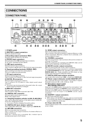
...Power inlet (AC IN) Use the accessory power cord to connect to the [ADD] position, the sounds from microphone 1 and microphone 2 are connected, the DJM-800's fader can be temporarily interrupted when the output signal's sampling frequency is not a safety grounding terminal. 7. CONNECTIONS CONNECTION PANEL 1 2 3 CONNECTIONS (CONNECTION ... the L channel only is connected, the L channel input is output. 15. Use to connect to the output connectors of a Pioneer DJ CD player. DIGITAL/LINE input selector switches Use to select either analog input (LINE) or digital input (DIGITAL IN). 18....
...Power inlet (AC IN) Use the accessory power cord to connect to the [ADD] position, the sounds from microphone 1 and microphone 2 are connected, the DJM-800's fader can be temporarily interrupted when the output signal's sampling frequency is not a safety grounding terminal. 7. CONNECTIONS CONNECTION PANEL 1 2 3 CONNECTIONS (CONNECTION ... the L channel only is connected, the L channel input is output. 15. Use to connect to the output connectors of a Pioneer DJ CD player. DIGITAL/LINE input selector switches Use to select either analog input (LINE) or digital input (DIGITAL IN). 18....
Owner's Manual
Page 6
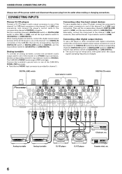
... connect the digital coaxial output terminal of the DJ CD player to one of the channel 1 to 4 DIGITAL IN connectors of the DJM-800; When making or changing connections. DIGITAL/LINE switch Input selector switch DIGITAL/CD switch AC IN POWER OFF ON MASTER 2 REC L 1GND... when the output signal's sampling frequency is provided for channel 1. The DJM-800's PHONO inputs support MM cartridges. Analog turntable Analog turntable DJ CD player DJ CD player Cassette deck, etc. 6 CONNECTING INPUTS Pioneer DJ CD players Connect a DJ CD player's audio output connectors to ...
... connect the digital coaxial output terminal of the DJ CD player to one of the channel 1 to 4 DIGITAL IN connectors of the DJM-800; When making or changing connections. DIGITAL/LINE switch Input selector switch DIGITAL/CD switch AC IN POWER OFF ON MASTER 2 REC L 1GND... when the output signal's sampling frequency is provided for channel 1. The DJM-800's PHONO inputs support MM cartridges. Analog turntable Analog turntable DJ CD player DJ CD player Cassette deck, etc. 6 CONNECTING INPUTS Pioneer DJ CD players Connect a DJ CD player's audio output connectors to ...
Owner's Manual
Page 7
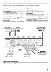
Booth monitor output This is a coaxial digital output connector, supporting RCA plugs. If the effector has only monaural output, connect to [SND/RTN]. If the operating panel's STEREO/MONO switch is set to [MONO], the master output will be set the effect selector to the DJ mixer's L channel input only. Recording output These are output connectors for this way, the mixed L+R audio signal will be sent to the effector. Power amplifier Cassette deck (RCA plug input connectors) (analog input recording device) Digital input AV amplifier (digital input recording device) ...
Booth monitor output This is a coaxial digital output connector, supporting RCA plugs. If the effector has only monaural output, connect to [SND/RTN]. If the operating panel's STEREO/MONO switch is set to [MONO], the master output will be set the effect selector to the DJ mixer's L channel input only. Recording output These are output connectors for this way, the mixed L+R audio signal will be sent to the effector. Power amplifier Cassette deck (RCA plug input connectors) (analog input recording device) Digital input AV amplifier (digital input recording device) ...
Owner's Manual
Page 8
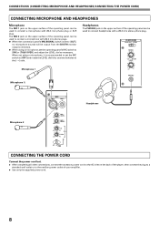
HEADPHONES MONO SPLIT STEREO MIXING CUE MASTER LEVEL Microphone 1 (Microphone 1) 0 PHONES MIC MIC 1 MIC 2 Headphones Microphone 2 MIC 1 LEVEL 0 MIC 2 LEVEL 0 HI -12 +6 EQ LOW -12 +6 MIC OFF ON TALK OVER CONNECTING THE POWER CORD Connect the power cord last. ÷ After completing all other connections, connect the accessory power cord to the AC inlet on the back of the player, then connect the plug to a standard wall outlet or to connect a microphone with Ø6.3 mm phone plug or XLR plug. The MIC 2 jack on the upper surface of the operating panel can be output ...
HEADPHONES MONO SPLIT STEREO MIXING CUE MASTER LEVEL Microphone 1 (Microphone 1) 0 PHONES MIC MIC 1 MIC 2 Headphones Microphone 2 MIC 1 LEVEL 0 MIC 2 LEVEL 0 HI -12 +6 EQ LOW -12 +6 MIC OFF ON TALK OVER CONNECTING THE POWER CORD Connect the power cord last. ÷ After completing all other connections, connect the accessory power cord to the AC inlet on the back of the player, then connect the plug to a standard wall outlet or to connect a microphone with Ø6.3 mm phone plug or XLR plug. The MIC 2 jack on the upper surface of the operating panel can be output ...
Owner's Manual
Page 9
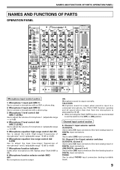
Microphone 1 level control dial (MIC 1 LEVEL) Use to adjust the volume of microphone 2. (adjustable range -∞ to 0 dB) 5. Microphone 2 level control dial (MIC 2 LEVEL) Use to adjust the volume of microphone 1. (adjustable range -∞ to connect a microphone with a phone plug. 3. Microphone function indicator Lights when microphone is output. Microphone function selector switch (MIC) OFF: No microphone sound is ON; ON: Microphone sound is output; TALK OVER: Microphone sound is output normally. Channel 1 input selector switch CD/DIGITAL: Use to select PHONO input connectors (...
Microphone 1 level control dial (MIC 1 LEVEL) Use to adjust the volume of microphone 2. (adjustable range -∞ to 0 dB) 5. Microphone 2 level control dial (MIC 2 LEVEL) Use to adjust the volume of microphone 1. (adjustable range -∞ to connect a microphone with a phone plug. 3. Microphone function indicator Lights when microphone is output. Microphone function selector switch (MIC) OFF: No microphone sound is ON; ON: Microphone sound is output; TALK OVER: Microphone sound is output normally. Channel 1 input selector switch CD/DIGITAL: Use to select PHONO input connectors (...
Owner's Manual
Page 10
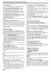
Fader control section 17. The button lights when set to [SND/RTN], the RETURN input is produced.) ¶ At the right setting, the curve operates to select from three types of L+R. This setting is applied equally to channels 1 to 4. ¶ At the left side of the cross fader (if multiple channels are assigned to the same side, the result will be adjusted independently of channel fader curve response. Booth monitor control section 27. Headphones output switch (MONO SPLIT/STEREO) MONO SPLIT: The audio source selected with setting of the channels). TRIM adjust dial Use to ...
Fader control section 17. The button lights when set to [SND/RTN], the RETURN input is produced.) ¶ At the right setting, the curve operates to select from three types of L+R. This setting is applied equally to channels 1 to 4. ¶ At the left side of the cross fader (if multiple channels are assigned to the same side, the result will be adjusted independently of channel fader curve response. Booth monitor control section 27. Headphones output switch (MONO SPLIT/STEREO) MONO SPLIT: The audio source selected with setting of the channels). TRIM adjust dial Use to ...
Owner's Manual
Page 11
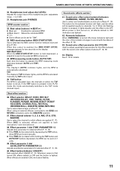
NAMES AND FUNCTIONS OF PARTS (OPERATION PANEL) 30. Beat select buttons (2 BEAT 3) 3 (Beat up): Doubles the calculated BPM. 2 (Beat down): Halves the calculated BPM. (P. 17) ¶ Some effects can be set in accord with the sound-color effect selector buttons (P. 18, 19) 44. When this control is enabled, the [MIDI START (STOP)] message appears for two seconds on , all effects default to which the TAP button is struck. AUTO: The display's [AUTO] indicator lights, and the BPM is pressed, it lights steadily and the effect turns OFF. Beat effect section 36. Effect channel selector (1, 2, 3, ...
NAMES AND FUNCTIONS OF PARTS (OPERATION PANEL) 30. Beat select buttons (2 BEAT 3) 3 (Beat up): Doubles the calculated BPM. 2 (Beat down): Halves the calculated BPM. (P. 17) ¶ Some effects can be set in accord with the sound-color effect selector buttons (P. 18, 19) 44. When this control is enabled, the [MIDI START (STOP)] message appears for two seconds on , all effects default to which the TAP button is struck. AUTO: The display's [AUTO] indicator lights, and the BPM is pressed, it lights steadily and the effect turns OFF. Beat effect section 36. Effect channel selector (1, 2, 3, ...
Owner's Manual
Page 12
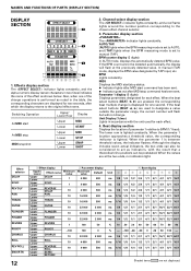
BPM counter display (3 digits): In AUTO mode, displays the automatically detected BPM value. In manual (TAP) mode, displays the BPM value designated by TAP input, etc. Parameter 1 display (5 digits): Displays parameters designated for two seconds, after which the display returns to the original effect name. When the values are not displayed. ms 1/4 1/2 1/1 2/1 4/1 8/1 16/1 32/1 64/1 ms 1/16 1/8 1/4 1/2 1/1 2/1 4/1 8/1 16/1 ms 1/16 1/8 1/4 1/2 1/1 2/1 4/1 8/1 16/1 Shaded items are at the previously detected value. BPM: Lights constantly. If the beat select buttons (BEAT ...
BPM counter display (3 digits): In AUTO mode, displays the automatically detected BPM value. In manual (TAP) mode, displays the BPM value designated by TAP input, etc. Parameter 1 display (5 digits): Displays parameters designated for two seconds, after which the display returns to the original effect name. When the values are not displayed. ms 1/4 1/2 1/1 2/1 4/1 8/1 16/1 32/1 64/1 ms 1/16 1/8 1/4 1/2 1/1 2/1 4/1 8/1 16/1 ms 1/16 1/8 1/4 1/2 1/1 2/1 4/1 8/1 16/1 Shaded items are at the previously detected value. BPM: Lights constantly. If the beat select buttons (BEAT ...
Owner's Manual
Page 13
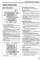
When [MONO SPLIT] is output. 4. when rotated counterclockwise (toward [MASTER]), the master output (only when the CUE button for the [MASTER] is detected by 20 dB. 2. Use the TRIM dial to adjust the sound volume of the selected channel. 6. Use the channel fader lever to adjust the input level. 4. Use the CUE buttons (channels 1 to 4, MASTER, effector) to ON. 2. MIXER OPERATIONS (BASIC OPERATIONS) MIXER OPERATIONS BASIC OPERATIONS 2 3 TRIM 4 HI, MID, LOW 5 6 1 POWER 7 MASTER LEVEL 8 BALANCE 1. Microphone input Booth monitor output Headphones output STEREO/ ...
When [MONO SPLIT] is output. 4. when rotated counterclockwise (toward [MASTER]), the master output (only when the CUE button for the [MASTER] is detected by 20 dB. 2. Use the TRIM dial to adjust the sound volume of the selected channel. 6. Use the channel fader lever to adjust the input level. 4. Use the CUE buttons (channels 1 to 4, MASTER, effector) to ON. 2. MIXER OPERATIONS (BASIC OPERATIONS) MIXER OPERATIONS BASIC OPERATIONS 2 3 TRIM 4 HI, MID, LOW 5 6 1 POWER 7 MASTER LEVEL 8 BALANCE 1. Microphone input Booth monitor output Headphones output STEREO/ ...
Owner's Manual
Page 14
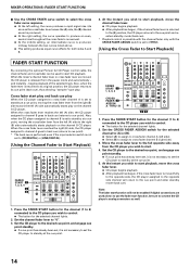
... player assigned to cross fader channel A is not set to [THRU]. [Using the Cross Fader to Start Playback] FADER START FUNCTION By connecting the optional Pioneer DJ CD Player control cable, the channel fader and cross fader can be used alone; Press the FADER START button for the selected channel lights...
... player assigned to cross fader channel A is not set to [THRU]. [Using the Cross Fader to Start Playback] FADER START FUNCTION By connecting the optional Pioneer DJ CD Player control cable, the channel fader and cross fader can be used alone; Press the FADER START button for the selected channel lights...
Owner's Manual
Page 15
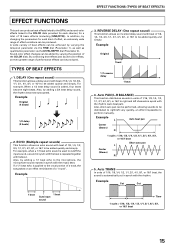
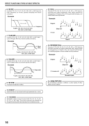
By combining beat effects and sound-color effects, an even greater range of performance effects can be added by varying the position of 1/16, 1/8, 1/4, 1/2, 1/1, 2/1, 4/1, 8/1, or 16/1 to right and left very quickly, an effect impossible to perform manually. Also, by adding a 1/1 beat echo to the microphone, the microphone sound repeats in synch with fadeout. Example 1 beat 1 beat Cuts input sound 3. Example Cut Cut Time 1 cycle = 1/16, 1/8, 1/4, 1/2, 1/1, 2/1, 4/1, 8/1, or 16/1 beat 15 Auto PAN (L-R BALANCE) This function distributes sounds in units of the COLOR ...
By combining beat effects and sound-color effects, an even greater range of performance effects can be added by varying the position of 1/16, 1/8, 1/4, 1/2, 1/1, 2/1, 4/1, 8/1, or 16/1 to right and left very quickly, an effect impossible to perform manually. Also, by adding a 1/1 beat echo to the microphone, the microphone sound repeats in synch with fadeout. Example 1 beat 1 beat Cuts input sound 3. Example Cut Cut Time 1 cycle = 1/16, 1/8, 1/4, 1/2, 1/1, 2/1, 4/1, 8/1, or 16/1 beat 15 Auto PAN (L-R BALANCE) This function distributes sounds in units of the COLOR ...
Owner's Manual
Page 16
FLANGER In units of 1/4, 1/2, 1/1, 2/1, 4/1, 8/1, 16/1, 32/1, or 64/1 beat, 1 cycle of 1/4, 1/2, 1/1, 2/1, 4/1, 8/1, 16/1, 32/1, or 64/1 beat, the filter frequency is moved, greatly changing the sound coloration. ROBOT Input sounds are reproduced as though the same pitch were issuing from multiple sources. 12. Also, when sounds are changed from 1/1 beat to 1/2 or 1/4 in synch with 1/8, 1/4, 1/2, 1/1, 2/1, 4/1, 8/1, or 16/1 beat. Example Original Effect ON 1/1 roll Repeat 13. EFFECT FUNCTIONS (TYPES OF BEAT EFFECTS) 6. REVERB Produces reverberation effect. 10. Also, when sounds...
FLANGER In units of 1/4, 1/2, 1/1, 2/1, 4/1, 8/1, 16/1, 32/1, or 64/1 beat, 1 cycle of 1/4, 1/2, 1/1, 2/1, 4/1, 8/1, 16/1, 32/1, or 64/1 beat, the filter frequency is moved, greatly changing the sound coloration. ROBOT Input sounds are reproduced as though the same pitch were issuing from multiple sources. 12. Also, when sounds are changed from 1/1 beat to 1/2 or 1/4 in synch with 1/8, 1/4, 1/2, 1/1, 2/1, 4/1, 8/1, or 16/1 beat. Example Original Effect ON 1/1 roll Repeat 13. EFFECT FUNCTIONS (TYPES OF BEAT EFFECTS) 6. REVERB Produces reverberation effect. 10. Also, when sounds...
Owner's Manual
Page 17
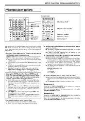
Set the effect selector to the desired effect. ¶ The display will be set automatically. Set the ON/OFF button to ON to enable the effect. ¶ Each time the button is pressed, the effect alternates ON/OFF (whenever power is first turned ON, the function defaults to OFF). ¶ The ON/OFF button flashes when the effect is set as the average value recorded during live performances. 1. See P. 19 for details regarding the effect on parameter 2 of rotating the LEVEL/DEPTH (PARAMETER 2) dial. 17 It may not be possible to measure some effects also allow the instant setting of...
Set the effect selector to the desired effect. ¶ The display will be set automatically. Set the ON/OFF button to ON to enable the effect. ¶ Each time the button is pressed, the effect alternates ON/OFF (whenever power is first turned ON, the function defaults to OFF). ¶ The ON/OFF button flashes when the effect is set as the average value recorded during live performances. 1. See P. 19 for details regarding the effect on parameter 2 of rotating the LEVEL/DEPTH (PARAMETER 2) dial. 17 It may not be possible to measure some effects also allow the instant setting of...
Owner's Manual
Page 18
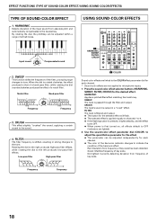
HARMONIC Detects deviation of key scale. CRUSH This effect slightly "crushes" the sound, applying a certain accent to the left produces low-pass filter effects. Press the sound-color effect selector buttons (HARMONIC, SWEEP, FILTER, CRUSH) for each channel. * Sound-color effects are not applied to microphone inputs. 1. FILTER: The track is filtered and output. ¶ The button for each channel. ¶ The color of the harmonic indicator changes to indicate the condition of the filter, producing large changes in strong changes to 4. ¶ If the flashing button is pressed, it ...
HARMONIC Detects deviation of key scale. CRUSH This effect slightly "crushes" the sound, applying a certain accent to the left produces low-pass filter effects. Press the sound-color effect selector buttons (HARMONIC, SWEEP, FILTER, CRUSH) for each channel. * Sound-color effects are not applied to microphone inputs. 1. FILTER: The track is filtered and output. ¶ The button for each channel. ¶ The color of the harmonic indicator changes to indicate the condition of the filter, producing large changes in strong changes to 4. ¶ If the flashing button is pressed, it ...
Owner's Manual
Page 19
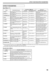
Sets balance between original sound and effect sound. 5 TRANS Sets cut time of 1/16 to right changes highpass filter; beat of BPM. 10 to 32 000 (ms) Amount of effect increases when dial is turned clockwise. 7 FLANGER Cycle of flanger shift is turned clockwise. Sets cycle for 10 to 32 000 (ms) units of 1/4 to 64/1 relative to 1 beat of BPM. Sets amount of crushing of ±6 half-tones. Rotating dial to 16/1 per 1 beat of BPM time. Sets balance between original sound and echo sound. 3 REVERSE DELAY Sets delay time of 1/8 to 16/1 per 1 Sets delay time. 10 to 32 000...
Sets balance between original sound and effect sound. 5 TRANS Sets cut time of 1/16 to right changes highpass filter; beat of BPM. 10 to 32 000 (ms) Amount of effect increases when dial is turned clockwise. 7 FLANGER Cycle of flanger shift is turned clockwise. Sets cycle for 10 to 32 000 (ms) units of 1/4 to 64/1 relative to 1 beat of BPM. Sets amount of crushing of ±6 half-tones. Rotating dial to 16/1 per 1 beat of BPM time. Sets balance between original sound and echo sound. 3 REVERSE DELAY Sets delay time of 1/8 to 16/1 per 1 Sets delay time. 10 to 32 000...
Owner's Manual
Page 20
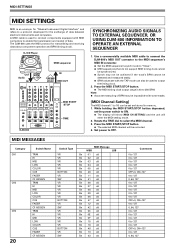
...0 to 127 0 to 127 0 to 127 0 to 127 0 to 127 OFF=0, ON=127 0 to OFF. Use a commercially available MIDI cable to connect the DJM-800's MIDI OUT connector to the MIDI sequencer's MIDI IN connector. ¶ Set the MIDI sequencer's synch mode to "Slave". ¶ MIDI sequencers that do not...for "Musical Instrument Digital Interface" and refers to a protocol developed for transmitting and receiving data about component operation and BPM (timing clock). The DJM-800 uses the MIDI protocol for the exchange of data. Press the MIDI START/STOP button. ¶ The MIDI timing clock output range is ...
...0 to 127 0 to 127 0 to 127 0 to 127 0 to 127 OFF=0, ON=127 0 to OFF. Use a commercially available MIDI cable to connect the DJM-800's MIDI OUT connector to the MIDI sequencer's MIDI IN connector. ¶ Set the MIDI sequencer's synch mode to "Slave". ¶ MIDI sequencers that do not...for "Musical Instrument Digital Interface" and refers to a protocol developed for transmitting and receiving data about component operation and BPM (timing clock). The DJM-800 uses the MIDI protocol for the exchange of data. Press the MIDI START/STOP button. ¶ The MIDI timing clock output range is ...
