Owner's Manual
Page 4
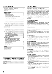
...Other functions ¶ A control cable can be used to connect the unit to a Pioneer DJ CD player, thus allowing playback to be linked to operation of the fader ("...play . CONTENTS CAUTIONS REGARDING HANDLING 3 CONFIRM ACCESSORIES 4 FEATURES 4 BEFORE USING CONNECTIONS 5 CONNECTION PANEL 5 CONNECTING INPUTS 6 CONNECTING EXTERNAL EFFECTORS, OUTPUT CONNECTORS 7 ABOUT MIDI CONNECTORS 7 CONNECTING MICROPHONE AND HEADPHONES ...19 MIDI SETTINGS 20 SYNCHRONIZING AUDIO SIGNALS TO EXTERNAL SEQUENCER, OR USING DJM-800 INFORMATION TO OPERATE AN EXTERNAL SEQUENCER 20 MIDI MESSAGES 20 PROGRAM CHANGE...
...Other functions ¶ A control cable can be used to connect the unit to a Pioneer DJ CD player, thus allowing playback to be linked to operation of the fader ("...play . CONTENTS CAUTIONS REGARDING HANDLING 3 CONFIRM ACCESSORIES 4 FEATURES 4 BEFORE USING CONNECTIONS 5 CONNECTION PANEL 5 CONNECTING INPUTS 6 CONNECTING EXTERNAL EFFECTORS, OUTPUT CONNECTORS 7 ABOUT MIDI CONNECTORS 7 CONNECTING MICROPHONE AND HEADPHONES ...19 MIDI SETTINGS 20 SYNCHRONIZING AUDIO SIGNALS TO EXTERNAL SEQUENCER, OR USING DJM-800 INFORMATION TO OPERATE AN EXTERNAL SEQUENCER 20 MIDI MESSAGES 20 PROGRAM CHANGE...
Owner's Manual
Page 5
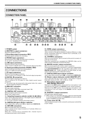
... safety grounding terminal. 7. DIGITAL/LINE input selector switches Use to attenuate the level of a Pioneer DJ CD player. Master output attenuator switch (MASTER ATT) Use to select either analog input (CD...) or digital input (DIGITAL IN). 13. CONNECTIONS CONNECTION PANEL 1 2 3 CONNECTIONS (CONNECTION PANEL) 4 5 6 7 8 AC IN POWER OFF ON MASTER 2 REC L 1GND R 2HOT 3COLD SIGNAL... 2 are connected, the DJM-800's fader can be temporarily interrupted when the output signal's sampling frequency is changed. 9.
... safety grounding terminal. 7. DIGITAL/LINE input selector switches Use to attenuate the level of a Pioneer DJ CD player. Master output attenuator switch (MASTER ATT) Use to select either analog input (CD...) or digital input (DIGITAL IN). 13. CONNECTIONS CONNECTION PANEL 1 2 3 CONNECTIONS (CONNECTION PANEL) 4 5 6 7 8 AC IN POWER OFF ON MASTER 2 REC L 1GND R 2HOT 3COLD SIGNAL... 2 are connected, the DJM-800's fader can be temporarily interrupted when the output signal's sampling frequency is changed. 9.
Owner's Manual
Page 7
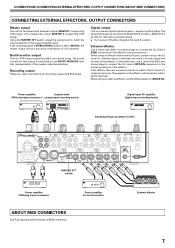
... sensitivity of MIDI connectors. When using an effector with balanced output MASTER 1 (supporting XLR plugs), and unbalanced output MASTER 2 (supporting RCA plugs). If the operating panel's STEREO/MONO switch is set to the effector. In this way, the mixed L+R audio signal will be sent to [MONO], the master output will be...
... sensitivity of MIDI connectors. When using an effector with balanced output MASTER 1 (supporting XLR plugs), and unbalanced output MASTER 2 (supporting RCA plugs). If the operating panel's STEREO/MONO switch is set to the effector. In this way, the mixed L+R audio signal will be sent to [MONO], the master output will be...
Owner's Manual
Page 8
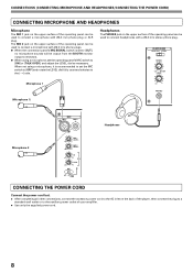
... (CONNECTING MICROPHONE AND HEADPHONES/CONNECTING THE POWER CORD) CONNECTING MICROPHONE AND HEADPHONES Microphone The MIC 1 jack on the upper surface of the operating panel can be used to the auxiliary power outlet of your amplifier. ÷ Use only the supplied power cord. 8 When not using a ...rotate the LEVEL dial fully counterclockwise to connect headphones with Ø6.3 mm phone plugs. ¶ When the connection panel's MIC SIGNAL switch is recommended to set the operating panel's MIC switch to [ON] or [TALK OVER], and adjust the LEVEL dial as necessary. Headphones The PHONES jack...
... (CONNECTING MICROPHONE AND HEADPHONES/CONNECTING THE POWER CORD) CONNECTING MICROPHONE AND HEADPHONES Microphone The MIC 1 jack on the upper surface of the operating panel can be used to the auxiliary power outlet of your amplifier. ÷ Use only the supplied power cord. 8 When not using a ...rotate the LEVEL dial fully counterclockwise to connect headphones with Ø6.3 mm phone plugs. ¶ When the connection panel's MIC SIGNAL switch is recommended to set the operating panel's MIC switch to [ON] or [TALK OVER], and adjust the LEVEL dial as necessary. Headphones The PHONES jack...
Owner's Manual
Page 9
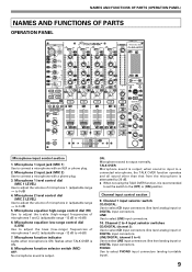
... (line level analog input) or DIGITAL input connectors. Microphone function indicator Lights when microphone is ON. 8. NAMES AND FUNCTIONS OF PARTS (OPERATION PANEL) NAMES AND FUNCTIONS OF PARTS OPERATION PANEL POWER MIC MIC 1 MIC 2 CD /DIGITAL LINE CD /DIGITAL LINE PHONO /DIGITAL LINE PHONO /DIGITAL PHONO MASTER LEVEL PROFESSIONAL MIXER 1 2 MIC 1 3 LEVEL...
... (line level analog input) or DIGITAL input connectors. Microphone function indicator Lights when microphone is ON. 8. NAMES AND FUNCTIONS OF PARTS (OPERATION PANEL) NAMES AND FUNCTIONS OF PARTS OPERATION PANEL POWER MIC MIC 1 MIC 2 CD /DIGITAL LINE CD /DIGITAL LINE PHONO /DIGITAL LINE PHONO /DIGITAL PHONO MASTER LEVEL PROFESSIONAL MIXER 1 2 MIC 1 3 LEVEL...
Owner's Manual
Page 10
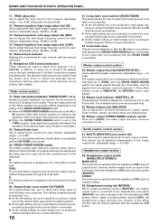
... set to select [MASTER]). Master output STEREO/MONO selector switch When set to monitor the desired source through headphones. NAMES AND FUNCTIONS OF PARTS (OPERATION PANEL) 11. A: The selected channel is assigned to the cross fader's A (left side of the cross fader (if multiple channels are assigned to the same side...
... set to select [MASTER]). Master output STEREO/MONO selector switch When set to monitor the desired source through headphones. NAMES AND FUNCTIONS OF PARTS (OPERATION PANEL) 11. A: The selected channel is assigned to the cross fader's A (left side of the cross fader (if multiple channels are assigned to the same side...
Owner's Manual
Page 11
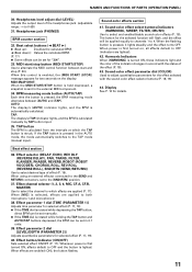
... section 36. Effect parameter 2 dial [LEVEL/DEPTH (PARAMETER 2)] Adjusts quantitative parameters for details. 11 Sound-color effects section 41. NAMES AND FUNCTIONS OF PARTS (OPERATION PANEL) 30. MIDI SNAP SHOT: When the MIDI START/STOP button is held depressed, a snapshot is first turned ON, effects default to OFF (indicators are applied...
... section 36. Effect parameter 2 dial [LEVEL/DEPTH (PARAMETER 2)] Adjusts quantitative parameters for details. 11 Sound-color effects section 41. NAMES AND FUNCTIONS OF PARTS (OPERATION PANEL) 30. MIDI SNAP SHOT: When the MIDI START/STOP button is held depressed, a snapshot is first turned ON, effects default to OFF (indicators are applied...
Owner's Manual
Page 13
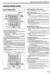
...] is selected, use the MIC 2 LEVEL dial to [MONO], the master output becomes a monaural combination of the selected channel. 6. Set the connection panel's MIC SIGNAL switch to select whether microphone sounds are output to the booth monitor. ¶ When set to the [ADD] position, microphone sounds are ...ASSIGN switch to either cross fader channel A or channel B, and operate the cross fader lever. ¶ When not using a DIGITAL input, the connection panel's DIGITAL/ CD switch or DIGITAL/LINE switch must be set to [TALK OVER], any time a sound of three characteristic curves. 7 Use the CH ...
...] is selected, use the MIC 2 LEVEL dial to [MONO], the master output becomes a monaural combination of the selected channel. 6. Set the connection panel's MIC SIGNAL switch to select whether microphone sounds are output to the booth monitor. ¶ When set to the [ADD] position, microphone sounds are ...ASSIGN switch to either cross fader channel A or channel B, and operate the cross fader lever. ¶ When not using a DIGITAL input, the connection panel's DIGITAL/ CD switch or DIGITAL/LINE switch must be set to [TALK OVER], any time a sound of three characteristic curves. 7 Use the CH ...
Owner's Manual
Page 22
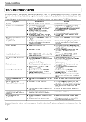
... Remedy ÷ Connect to power outlet. ÷ Set input selector to playback component. ÷ Set the rear panel's DIGITAL/CD input selector switch or DIGITAL/LINE input selector switch to match the component being played. ÷ Connect ...Cause ÷ The power cord has not been connected. ÷ Input selector is set incorrectly. ÷ The rear panel's DIGITAL/CD input selector switch or DIGITAL/LINE input selector switch is set incorrectly. ÷ Connection cables are connected incorrectly... even after checking the following items, contact your dealer or nearest PIONEER service center.
... Remedy ÷ Connect to power outlet. ÷ Set input selector to playback component. ÷ Set the rear panel's DIGITAL/CD input selector switch or DIGITAL/LINE input selector switch to match the component being played. ÷ Connect ...Cause ÷ The power cord has not been connected. ÷ Input selector is set incorrectly. ÷ The rear panel's DIGITAL/CD input selector switch or DIGITAL/LINE input selector switch is set incorrectly. ÷ Connection cables are connected incorrectly... even after checking the following items, contact your dealer or nearest PIONEER service center.