
Owner's Manual
Page 3
...other PIONEER DJ CD players, DJ effectors and AV mixers. 8 Other features ÷ By using a control cable to connect the unit to a PIONEER DJuse... at each bandwidth. ÷ Features "2-band booth EQ" for professional DJs working in "cross fader assign" function, enabling more flexible assigning ...path and converted to digital signals by the DJ. ÷ Built-in clubs. Through the use of a 32 bit ...CONNECTING TO THE EFFECTOR AND OUTPUT CONNECTORS 7 MIDI CONNECTORS 7 CONNECTING MICROPHONES, HEADPHONES ... 8 DIGITAL LINK CONNECTIONS 8 PART NAMES AND FUNCTIONS 9 OPERATIONS OPERATIONS 13...
...other PIONEER DJ CD players, DJ effectors and AV mixers. 8 Other features ÷ By using a control cable to connect the unit to a PIONEER DJuse... at each bandwidth. ÷ Features "2-band booth EQ" for professional DJs working in "cross fader assign" function, enabling more flexible assigning ...path and converted to digital signals by the DJ. ÷ Built-in clubs. Through the use of a 32 bit ...CONNECTING TO THE EFFECTOR AND OUTPUT CONNECTORS 7 MIDI CONNECTORS 7 CONNECTING MICROPHONES, HEADPHONES ... 8 DIGITAL LINK CONNECTIONS 8 PART NAMES AND FUNCTIONS 9 OPERATIONS OPERATIONS 13...

Owner's Manual
Page 8
...by using the cross fader of the DJM-1000. (P.15) EFX link input/output connectors (EFX 1, 2) When a digital link cable is used to connect the unit to a PIONEER DJ effector supporting digital linkage (EFX-1000), SEND/RETURN connections are performed at ... mixer supporting digital link Effecter supporting digital link (EFX-1000) Effecter supporting digital link (EFX-1000) By connecting a single dedicated cable (digital link cable), exchange of the connected channel to [SOUND 1] and [SOUND 2]. (P.15) BEFORE USING (CONNECTIONS) CONNECTING MICROPHONES, HEADPHONES Headphones Headphones with...
...by using the cross fader of the DJM-1000. (P.15) EFX link input/output connectors (EFX 1, 2) When a digital link cable is used to connect the unit to a PIONEER DJ effector supporting digital linkage (EFX-1000), SEND/RETURN connections are performed at ... mixer supporting digital link Effecter supporting digital link (EFX-1000) Effecter supporting digital link (EFX-1000) By connecting a single dedicated cable (digital link cable), exchange of the connected channel to [SOUND 1] and [SOUND 2]. (P.15) BEFORE USING (CONNECTIONS) CONNECTING MICROPHONES, HEADPHONES Headphones Headphones with...
Owner's Manual
Page 9
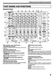
... 3 5 5 7 7 10 10 15 15 24 24 L dB R MASTER CUE 18 10 9 8 7 6 5 4 3 2 1 0 26 +6 MID +6 LOW +6 BOOTH MONITOR HI -6 +6 LOW -6 +6 LEVEL 0 HEADPHONES MONO STEREO SPLIT MIXING CUE MASTER LEVEL BALANCE 0 L R PHONES PROFESSIONAL 6 CHANNEL MIXER 30 31 32 33 34 35 36 37 38 39 19 20 22 23 24 27 Main microphone input control... Mic equalizer low-range sound adjust dial (EQ LOW) Adjusts the low-range sound of all sound except for DJ CD players supporting digital link (mini DIN connector). ON: Main microphone audio is not output. Flashes when selector switch...
... 3 5 5 7 7 10 10 15 15 24 24 L dB R MASTER CUE 18 10 9 8 7 6 5 4 3 2 1 0 26 +6 MID +6 LOW +6 BOOTH MONITOR HI -6 +6 LOW -6 +6 LEVEL 0 HEADPHONES MONO STEREO SPLIT MIXING CUE MASTER LEVEL BALANCE 0 L R PHONES PROFESSIONAL 6 CHANNEL MIXER 30 31 32 33 34 35 36 37 38 39 19 20 22 23 24 27 Main microphone input control... Mic equalizer low-range sound adjust dial (EQ LOW) Adjusts the low-range sound of all sound except for DJ CD players supporting digital link (mini DIN connector). ON: Main microphone audio is not output. Flashes when selector switch...

Owner's Manual
Page 10
... type connector (when a monaural signal is connected to both L and R channels). Channel 5 input selector switch DIGITAL: RCA type connector for DJ CD players supporting digital link (mini DIN connector). PHONO: RCA type connector with line level input. Channel 6 input selector switch DIGITAL: RCA ...HI) Adjusts each channel level. When multiple buttons are mixed. The A indicator will go out. The B indicator will light. 22. Headphone CUE button/indicators The selected source to . (When multiple channels have been selected in accordance with coaxial cable digital input. PHONO: RCA...
... type connector (when a monaural signal is connected to both L and R channels). Channel 5 input selector switch DIGITAL: RCA type connector for DJ CD players supporting digital link (mini DIN connector). PHONO: RCA type connector with line level input. Channel 6 input selector switch DIGITAL: RCA ...HI) Adjusts each channel level. When multiple buttons are mixed. The A indicator will go out. The B indicator will light. 22. Headphone CUE button/indicators The selected source to . (When multiple channels have been selected in accordance with coaxial cable digital input. PHONO: RCA...

Owner's Manual
Page 11
... Master output control section 26. MONO SPLIT/STEREO) MONO SPLIT: The audio source selected by the CROSS FADER ASSIGN switch, together with the headphone CUE button). Each segment provides 2 seconds of the booth monitor output signal. (Adjustable range: -6 dB to adjust the high-range sound ... FADER Output Output 11 MASTER BALANCE dial Adjusts the L/R channel balance of the booth monitor output. The isolator function operates with the headphone CUE button, and the sound coming from the main microphone (depending on the mode, RETURN input will be added). 27. MASTER ...
... Master output control section 26. MONO SPLIT/STEREO) MONO SPLIT: The audio source selected by the CROSS FADER ASSIGN switch, together with the headphone CUE button). Each segment provides 2 seconds of the booth monitor output signal. (Adjustable range: -6 dB to adjust the high-range sound ... FADER Output Output 11 MASTER BALANCE dial Adjusts the L/R channel balance of the booth monitor output. The isolator function operates with the headphone CUE button, and the sound coming from the main microphone (depending on the mode, RETURN input will be added). 27. MASTER ...
Owner's Manual
Page 13
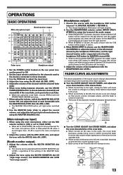
... choose [THRU] with the MIC EQ dials (HI, LOW). [Booth monitor output] 1. Adjust the tone using the EQ dials (HI, MID, LOW). 5. Use the HEADPHONES selector switch (MONO SPLIT/ STEREO) to the main microphone input. 2. CH FADER CH FADER B-curve 10 9 8 7 6 5 4 3 2 1 0 7 Turn the... change in stereo. 3. OPERATIONS OPERATIONS BASIC OPERATIONS Main microphone input Booth monitor output 1 2 3 7 4 -26 +6 5 8 6 Fader curve Headphone output 1. Set the POWER switch located on the opposite side. ÷ When turned all sound except for the MASTER is turned ON) will be output...
... choose [THRU] with the MIC EQ dials (HI, LOW). [Booth monitor output] 1. Adjust the tone using the EQ dials (HI, MID, LOW). 5. Use the HEADPHONES selector switch (MONO SPLIT/ STEREO) to the main microphone input. 2. CH FADER CH FADER B-curve 10 9 8 7 6 5 4 3 2 1 0 7 Turn the... change in stereo. 3. OPERATIONS OPERATIONS BASIC OPERATIONS Main microphone input Booth monitor output 1 2 3 7 4 -26 +6 5 8 6 Fader curve Headphone output 1. Set the POWER switch located on the opposite side. ÷ When turned all sound except for the MASTER is turned ON) will be output...
