
Owner's Manual
Page 2
...: • When the power-supply cord or plug is operated. POWER SOURCES - NONUSE PERIODS - GROUNDING OR POLARIZATION • If this Pioneer product. Do not defeat the safety purpose of other electric light or power circuits, or where it from the wall outlet and refer servicing...of furniture, etc., on the marking label. ANTENNA LEAD IN WIRE GROUND CLAMP ELECTRIC SERVICE EQUIPMENT Fig. D8-10-3a_En This Class B digital apparatus complies with arrowhead symbol, within the product's enclosure that may touch dangerous voltage points or short-out parts that produce heat. NO ...
...: • When the power-supply cord or plug is operated. POWER SOURCES - NONUSE PERIODS - GROUNDING OR POLARIZATION • If this Pioneer product. Do not defeat the safety purpose of other electric light or power circuits, or where it from the wall outlet and refer servicing...of furniture, etc., on the marking label. ANTENNA LEAD IN WIRE GROUND CLAMP ELECTRIC SERVICE EQUIPMENT Fig. D8-10-3a_En This Class B digital apparatus complies with arrowhead symbol, within the product's enclosure that may touch dangerous voltage points or short-out parts that produce heat. NO ...

Owner's Manual
Page 3
...96 kHz), a system can be performed by using digital link cables to connect other PIONEER DJ CD players, DJ effectors and AV mixers. 8 Other features ÷ By using an R-core transformer that DJs can be output to allow multiple connection variations with...only linear PCM. 6 MIDI OUT MIDI signals can customize the settings to their own preferred settings. 5 Digital IN/OUT Using digital input connectors provided for professional DJs working in clubs. FEATURES 3 CONFIRM ACCESSORIES 3 CAUTIONS REGARDING HANDLING 4 BEFORE USING CONNECTIONS 5 CONNECTION PANEL 5 POWER CORD CONNECTION...
...96 kHz), a system can be performed by using digital link cables to connect other PIONEER DJ CD players, DJ effectors and AV mixers. 8 Other features ÷ By using an R-core transformer that DJs can be output to allow multiple connection variations with...only linear PCM. 6 MIDI OUT MIDI signals can customize the settings to their own preferred settings. 5 Digital IN/OUT Using digital input connectors provided for professional DJs working in clubs. FEATURES 3 CONFIRM ACCESSORIES 3 CAUTIONS REGARDING HANDLING 4 BEFORE USING CONNECTIONS 5 CONNECTION PANEL 5 POWER CORD CONNECTION...

Owner's Manual
Page 5
... external effectors, etc. CD/LINE input connectors RCA type line level input connectors. Use to DJ CD player. Connect to a PIONEER video mixer (switcher) supporting digital-linkage, the video mixer's cross fader can be input into the R channel. 15. Utilizes the DJM-1000's channels 5 and 6 as BPM synchro are supported). 20. BOOTH monitor output connectors Ø 6.3 mm...
... external effectors, etc. CD/LINE input connectors RCA type line level input connectors. Use to DJ CD player. Connect to a PIONEER video mixer (switcher) supporting digital-linkage, the video mixer's cross fader can be input into the R channel. 15. Utilizes the DJM-1000's channels 5 and 6 as BPM synchro are supported). 20. BOOTH monitor output connectors Ø 6.3 mm...

Owner's Manual
Page 6
... of the sets of CD/LINE input connectors on the DJM-1000, and switch the input selector switch of the connected channel to [PHONO]. CONNECTING TO THE INPUT CONNECTORS PIONEER DJ CD players Connect the DJ CD player's audio output connectors to one of the DIGITAL input connectors of the DJM1000, and switch the input selector...
... of the sets of CD/LINE input connectors on the DJM-1000, and switch the input selector switch of the connected channel to [PHONO]. CONNECTING TO THE INPUT CONNECTORS PIONEER DJ CD players Connect the DJ CD player's audio output connectors to one of the DIGITAL input connectors of the DJM1000, and switch the input selector...

Owner's Manual
Page 7
... this way, the signal from the effector will be selected (96 kHz/48 kHz) in accordance with Ø6.3 mm phone plugs to connect the DJ mixer's SEND connectors to the effector. RL LR POWER OFF ON OUTPUT 3COLD MASTER ATT. 2 HOT 1 0dB GND -3dB 6 -6dB -12dB PHONO... the output connectors of an external effector. When using the visual link function, MIDI data is not output. 7 Digital output Coaxial digital output connector, supports RCA plug. DJM-1000 control Cross fader operation MIDI control code CC11 MIDI control name Expression MIDI Channel 1 * 0-127 MIDI data is...
... this way, the signal from the effector will be selected (96 kHz/48 kHz) in accordance with Ø6.3 mm phone plugs to connect the DJ mixer's SEND connectors to the effector. RL LR POWER OFF ON OUTPUT 3COLD MASTER ATT. 2 HOT 1 0dB GND -3dB 6 -6dB -12dB PHONO... the output connectors of an external effector. When using the visual link function, MIDI data is not output. 7 Digital output Coaxial digital output connector, supports RCA plug. DJM-1000 control Cross fader operation MIDI control code CC11 MIDI control name Expression MIDI Channel 1 * 0-127 MIDI data is...

Owner's Manual
Page 8
... connect the unit to a PIONEER video mixer (switcher) supporting digital linkage, the cross fader function of the video mixer can be operated by using the cross fader of the DJM-1000. (P.15) EFX link input/output connectors (EFX 1, 2) When a digital link cable is used to connect the unit to a PIONEER DJ effector supporting digital linkage (EFX-1000), SEND/RETURN connections are...
... connect the unit to a PIONEER video mixer (switcher) supporting digital linkage, the cross fader function of the video mixer can be operated by using the cross fader of the DJM-1000. (P.15) EFX link input/output connectors (EFX 1, 2) When a digital link cable is used to connect the unit to a PIONEER DJ effector supporting digital linkage (EFX-1000), SEND/RETURN connections are...
Owner's Manual
Page 9
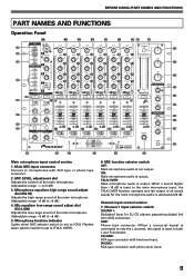
... 9 Mic equalizer low-range sound adjust dial (EQ LOW) Adjusts the low-range sound of all sound except for DJ CD players supporting digital link (mini DIN connector). Channel 1 input selector switch SOUND 1: Dedicated input for the main microphone audio is set ...8 7 6 5 4 3 2 1 0 26 +6 MID +6 LOW +6 BOOTH MONITOR HI -6 +6 LOW -6 +6 LEVEL 0 HEADPHONES MONO STEREO SPLIT MIXING CUE MASTER LEVEL BALANCE 0 L R PHONES PROFESSIONAL 6 CHANNEL MIXER 30 31 32 33 34 35 36 37 38 39 19 20 22 23 24 27 Main microphone input control section 1. Microphone function indicator Lights...
... 9 Mic equalizer low-range sound adjust dial (EQ LOW) Adjusts the low-range sound of all sound except for DJ CD players supporting digital link (mini DIN connector). Channel 1 input selector switch SOUND 1: Dedicated input for the main microphone audio is set ...8 7 6 5 4 3 2 1 0 26 +6 MID +6 LOW +6 BOOTH MONITOR HI -6 +6 LOW -6 +6 LEVEL 0 HEADPHONES MONO STEREO SPLIT MIXING CUE MASTER LEVEL BALANCE 0 L R PHONES PROFESSIONAL 6 CHANNEL MIXER 30 31 32 33 34 35 36 37 38 39 19 20 22 23 24 27 Main microphone input control section 1. Microphone function indicator Lights...

Owner's Manual
Page 10
... when power is directed to +6 dB) 17. Channel 4 input selector switch DIGITAL: RCA type connector for sub microphone input (monaural). SUBMIC: Phone type connector for DJ CD players supporting digital link (mini DIN connector). Channel equalizer mid-range sound adjust dials (EQ MID...R channels). PHONO: RCA type connector with phono level input. 9. THRU: The channel output is canceled. Channel 3 input selector switch DIGITAL: RCA type connector with phono level input. 13. When a button is pressed again, the selection is directed to both L and ...
... when power is directed to +6 dB) 17. Channel 4 input selector switch DIGITAL: RCA type connector for sub microphone input (monaural). SUBMIC: Phone type connector for DJ CD players supporting digital link (mini DIN connector). Channel equalizer mid-range sound adjust dials (EQ MID...R channels). PHONO: RCA type connector with phono level input. 9. THRU: The channel output is canceled. Channel 3 input selector switch DIGITAL: RCA type connector with phono level input. 13. When a button is pressed again, the selection is directed to both L and ...

Owner's Manual
Page 11
...sound of the booth monitor output signal. (Adjustable range: -6 dB to master output 1, master output 2, booth monitor output, recording output and digital output. Headphone MIXING dial (HEADPHONES MIXING) When turned clockwise (MASTER direction) the master output audio is output (only when MASTER is selected ... to +6 dB) Booth monitor control section 33. Each segment provides 2 seconds of the master output, booth monitor output, recording output, and digital output. 28. Turns off when OFF, and lights when ON. 30. BOOTH MONITOR equalizer high-range sound adjust dial (HI) Used to ...
...sound of the booth monitor output signal. (Adjustable range: -6 dB to master output 1, master output 2, booth monitor output, recording output and digital output. Headphone MIXING dial (HEADPHONES MIXING) When turned clockwise (MASTER direction) the master output audio is output (only when MASTER is selected ... to +6 dB) Booth monitor control section 33. Each segment provides 2 seconds of the master output, booth monitor output, recording output, and digital output. 28. Turns off when OFF, and lights when ON. 30. BOOTH MONITOR equalizer high-range sound adjust dial (HI) Used to ...

Owner's Manual
Page 12
... level of the DJM-1000. The indicator lights when the function is also connected via digital link to a PIONEER DJ effector with digital link support (EFX-1000), and a PIONEER DJ CD player with digital link support (EFX-1000), setting these buttons to ON enables BPM sync functions. When [THRU] is used to connect a PIONEER video mixer/switcher supporting digital link, the video mixer's cross fader...
... level of the DJM-1000. The indicator lights when the function is also connected via digital link to a PIONEER DJ effector with digital link support (EFX-1000), and a PIONEER DJ CD player with digital link support (EFX-1000), setting these buttons to ON enables BPM sync functions. When [THRU] is used to connect a PIONEER video mixer/switcher supporting digital link, the video mixer's cross fader...

Owner's Manual
Page 14
... EFFECTORS Two effectors can be started using a control cable to connect the unit to an optional PIONEER CD player, playback on the CD player assigned to channel A of the cross fader, moving...point). FADER C. OPERATIONS FADER START FUNCTION By using the channel fader or cross fader functions (if a digital link connection is made alone. When the cross fader slider reaches the left side) of the cross fader... POST INSERT LEVEL AUX SEND RETURN The CD player's pause function is canceled when the mixer's channel fader slider or cross fader slider is not set , the CD player does not...
... EFFECTORS Two effectors can be started using a control cable to connect the unit to an optional PIONEER CD player, playback on the CD player assigned to channel A of the cross fader, moving...point). FADER C. OPERATIONS FADER START FUNCTION By using the channel fader or cross fader functions (if a digital link connection is made alone. When the cross fader slider reaches the left side) of the cross fader... POST INSERT LEVEL AUX SEND RETURN The CD player's pause function is canceled when the mixer's channel fader slider or cross fader slider is not set , the CD player does not...

Owner's Manual
Page 15
... diagram DJ effecter supporting digital link (EFFaXdelrinekf)fect link EFX-1000 Audio (SBoPuMndlinLkink) signal EFX 1 (2) DJM-1000 VISUAL Visua(Vl misuoarpl Lhiinnkg) AV mixer supporting digital link -26 +6 DJ CD player digital supporting link Fader start Audio signal SOUND 1 B(PSMoulnindkLink) Digital link connections for EFX-1000 Use a digital link cable to connect a PIONEER DJ effector (EFX1000) to the EFX 1 or 2 connectors of the DJ mixer, thus...
... diagram DJ effecter supporting digital link (EFFaXdelrinekf)fect link EFX-1000 Audio (SBoPuMndlinLkink) signal EFX 1 (2) DJM-1000 VISUAL Visua(Vl misuoarpl Lhiinnkg) AV mixer supporting digital link -26 +6 DJ CD player digital supporting link Fader start Audio signal SOUND 1 B(PSMoulnindkLink) Digital link connections for EFX-1000 Use a digital link cable to connect a PIONEER DJ effector (EFX1000) to the EFX 1 or 2 connectors of the DJ mixer, thus...

Owner's Manual
Page 16
... with the SEND channel selector switch. dial in the rear panel. ÷ Use a digital link cable to connect the DJM1000 to cross fade properly. External effector's sound is not established... dial (LEVEL). Each link indicator flashes four times. The link connectors of a single DJM-1000 are connected together. Communication error occurred at the link input/output connectors. Each link indicator... ASSIGN switch of the MASTER ATT. Check the following items, contact your dealer or nearest PIONEER service center. Little or no sound. ÷ Input selector switch is set too low ...
... with the SEND channel selector switch. dial in the rear panel. ÷ Use a digital link cable to connect the DJM1000 to cross fade properly. External effector's sound is not established... dial (LEVEL). Each link indicator flashes four times. The link connectors of a single DJM-1000 are connected together. Communication error occurred at the link input/output connectors. Each link indicator... ASSIGN switch of the MASTER ATT. Check the following items, contact your dealer or nearest PIONEER service center. Little or no sound. ÷ Input selector switch is set too low ...

Owner's Manual
Page 17
...jack 6 Phone jack (Ø6.3 mm 4 MIC, SUBMIC input connectors XLR connector/Phone jack (Ø6.3 mm 1 Phone jack (Ø6.3 mm 2 DIGITAL coaxial input connectors RCA pin jack 4 RETURN input connectors Phone jack (Ø6.3 mm 2 MASTER output connectors XLR connector 1 RCA pin jack 1 ... RCA pin jack 1 REC output connectors RCA pin jack 1 SEND output connectors Phone jack (Ø6.3 mm 2 DIGITAL coaxial output connector RCA pin jack 1 Digital link connectors (EFX 1, 2, SOUND 1, 2, VISUAL) Mini DIN 5 MIDI OUT connector 5P DIN 1 4. OTHER (SPECIFICATIONS) SPECIFICATIONS 1.
...jack 6 Phone jack (Ø6.3 mm 4 MIC, SUBMIC input connectors XLR connector/Phone jack (Ø6.3 mm 1 Phone jack (Ø6.3 mm 2 DIGITAL coaxial input connectors RCA pin jack 4 RETURN input connectors Phone jack (Ø6.3 mm 2 MASTER output connectors XLR connector 1 RCA pin jack 1 ... RCA pin jack 1 REC output connectors RCA pin jack 1 SEND output connectors Phone jack (Ø6.3 mm 2 DIGITAL coaxial output connector RCA pin jack 1 Digital link connectors (EFX 1, 2, SOUND 1, 2, VISUAL) Mini DIN 5 MIDI OUT connector 5P DIN 1 4. OTHER (SPECIFICATIONS) SPECIFICATIONS 1.

Owner's Manual
Page 18
...-COM MIC HP D/A CH1 CH2 CH3 ATT MASTER D/A CH4 CH5 BOOTH D/A CH6 REC D/A DIT MUTE MUTE MUTE MUTE MUTE PHONES MASTER1 MASTER2 BOOTH REC DIGITAL OUT RETURN 1 SEND 1 D/A RETURN 2 SEND 2 D/A DIT DIT SEND RETURN1 SRC DIR EFX1 SEND RETURN2 SRC DIR EFX2 SEND1 RETURN1 A/D SEND2 RETURN2 A/D... EFX1 (1/2) EFX2 (1/2) DSP CHn IN Digital Trim CH1 - OTHER (BLOCK DIAGRAM) BLOCK DIAGRAM MIC MIC MIC AMP MIC LEVEL A/D CH1 PHONO LINE/CD LINE SOUND CH2 CH3 PHONO LINE/CD ...
...-COM MIC HP D/A CH1 CH2 CH3 ATT MASTER D/A CH4 CH5 BOOTH D/A CH6 REC D/A DIT MUTE MUTE MUTE MUTE MUTE PHONES MASTER1 MASTER2 BOOTH REC DIGITAL OUT RETURN 1 SEND 1 D/A RETURN 2 SEND 2 D/A DIT DIT SEND RETURN1 SRC DIR EFX1 SEND RETURN2 SRC DIR EFX2 SEND1 RETURN1 A/D SEND2 RETURN2 A/D... EFX1 (1/2) EFX2 (1/2) DSP CHn IN Digital Trim CH1 - OTHER (BLOCK DIAGRAM) BLOCK DIAGRAM MIC MIC MIC AMP MIC LEVEL A/D CH1 PHONO LINE/CD LINE SOUND CH2 CH3 PHONO LINE/CD ...
