User manual
Page 3
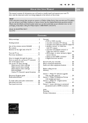
...number which are being displayed at the back of your television set or on the packaging, ready, before calling the Philips helpline 1-888-PHILIPS (744-5477) Model: 42-50-63PF9631D/37 Serial No: Contents Safety warnings 2 Getting started 3 Use of the remote control RC4403 6 My content... to initially install and operate your recorder 49 Select connected equipment 50 Audio and video equipment buttons 50 Before calling service 51 Glossary 52 Annex 1 - Philips TV-Slideshow Format with your new TV. Help? If this User Manual EN This manual contains all information you can ...
...number which are being displayed at the back of your television set or on the packaging, ready, before calling the Philips helpline 1-888-PHILIPS (744-5477) Model: 42-50-63PF9631D/37 Serial No: Contents Safety warnings 2 Getting started 3 Use of the remote control RC4403 6 My content... to initially install and operate your recorder 49 Select connected equipment 50 Audio and video equipment buttons 50 Before calling service 51 Glossary 52 Annex 1 - Philips TV-Slideshow Format with your new TV. Help? If this User Manual EN This manual contains all information you can ...
User manual
Page 5
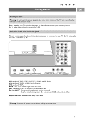
... before hanging it on the wall, first connect your TV. Getting started EN Before you start Warning: do not insert the power plug into the mains at the bottom of audio and video devices that can handle VIDEO or S-VIDEO, L/R Audio and USB, Service UART : For use only by authorized ...service personnel. Overview of the rear connector panel There is a wide range of the TV and in a wall socket before making any connections. 3...
... before hanging it on the wall, first connect your TV. Getting started EN Before you start Warning: do not insert the power plug into the mains at the bottom of audio and video devices that can handle VIDEO or S-VIDEO, L/R Audio and USB, Service UART : For use only by authorized ...service personnel. Overview of the rear connector panel There is a wide range of the TV and in a wall socket before making any connections. 3...
User manual
Page 6
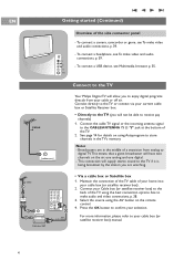
Connect to the TV CABLE o ANTENNA 75 Your Philips Digital TV will allow you will not be able to receive pay channels) 1. See page 14 for details on using the best connection options. Notes: - Connect your current cable box or Satellite Receiver box. • Directly to the TV (you to enjoy digital ... one digital. - To connect a USB device, see To make video and audio connections, p. 39. - Connect directly to the TV or connect via your Cable box (or satellite receiver box) to the back of the TV using Autoprogram to the TV if it is being broadcast by the station you are in the...
Connect to the TV CABLE o ANTENNA 75 Your Philips Digital TV will allow you will not be able to receive pay channels) 1. See page 14 for details on using the best connection options. Notes: - Connect your current cable box or Satellite Receiver box. • Directly to the TV (you to enjoy digital ... one digital. - To connect a USB device, see To make video and audio connections, p. 39. - Connect directly to the TV or connect via your Cable box (or satellite receiver box) to the back of the TV using Autoprogram to the TV if it is being broadcast by the station you are in the...
User manual
Page 9
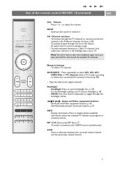
...modes. to display (when available) information about the selected TV channel and program or accessory device. Audio and Video equipment buttons See Audio and Video equipment buttons, p. 50. MUTE Interrupt the sound or restore it. To switch the TV on from standby mode; - To select between the ...:You don't have searched for digital channels. AV/SOURCE Press repeatedly to select AV1, AV2, AV3, HDMI, Side or TV channels when in the Preferred channels list (see TV menus, Ambilight, p. 28. - MODE: Press this button repeatedly to where you have to switch Ambilight On or Off...
...modes. to display (when available) information about the selected TV channel and program or accessory device. Audio and Video equipment buttons See Audio and Video equipment buttons, p. 50. MUTE Interrupt the sound or restore it. To switch the TV on from standby mode; - To select between the ...:You don't have searched for digital channels. AV/SOURCE Press repeatedly to select AV1, AV2, AV3, HDMI, Side or TV channels when in the Preferred channels list (see TV menus, Ambilight, p. 28. - MODE: Press this button repeatedly to where you have to switch Ambilight On or Off...
User manual
Page 19
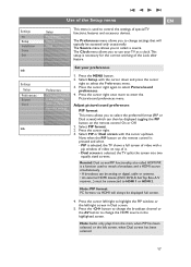
...the cursor right. 3. Select PIP or Dual screen with the cursor down . Now, when the PIP button on the remote control is selected, the TV splits the screen into two equally sized screens. Select Setup with the cursor up/down and press the cursor right to highlight the PIP window... Settings Setup Preferences Source Clock Info Use of the Setup menu EN Setup Preferences Source Clock This menu is selected, the TV shows a full screen of video with a pip window of video on top of it. - Features prefer. Menu preferences Reset AV settings 1. Press the cursor right again to enter the...
...the cursor right. 3. Select PIP or Dual screen with the cursor down . Now, when the PIP button on the remote control is selected, the TV splits the screen into two equally sized screens. Select Setup with the cursor up/down and press the cursor right to highlight the PIP window... Settings Setup Preferences Source Clock Info Use of the Setup menu EN Setup Preferences Source Clock This menu is selected, the TV shows a full screen of video with a pip window of video on top of it. - Features prefer. Menu preferences Reset AV settings 1. Press the cursor right again to enter the...
User manual
Page 22
...while minimizing disruption of the information disseminated by the cable operator.The standard SCTE18 defines an Emergency Alert signalling method for use by cable TV systems to signal emergencies to be ignored; - Select OSD. 2. Press the cursor right to be displayed when available; - Show...This allows you want the messages with high priority to be presented. The Emergency alert message with analogue video sources. - The message display will always be displayed. Important:When the TV clock is not possible: - Show emergency.. The start time + date - Always, when you ...
...while minimizing disruption of the information disseminated by the cable operator.The standard SCTE18 defines an Emergency Alert signalling method for use by cable TV systems to signal emergencies to be ignored; - Select OSD. 2. Press the cursor right to be displayed when available; - Show...This allows you want the messages with high priority to be presented. The Emergency alert message with analogue video sources. - The message display will always be displayed. Important:When the TV clock is not possible: - Show emergency.. The start time + date - Always, when you ...
User manual
Page 24
... Daylight saving Set your clock This allows you to use your source This menu allows you to identify the accessory devices you to the TV's Digital Audio in jack. Select Source in the Setup menu. 2. Select the appropriate input with a single cable to identify which your... a matching connector for the correct working of external inputs. 3. In the Source menu, assign the Digital Audio in antenna channels. See To make Video and Audio connections, Digital Surround receiver, p. 49. Auto clock mode 1. In such cases either clock extraction is taking a long time or there ...
... Daylight saving Set your clock This allows you to use your source This menu allows you to identify the accessory devices you to the TV's Digital Audio in jack. Select Source in the Setup menu. 2. Select the appropriate input with a single cable to identify which your... a matching connector for the correct working of external inputs. 3. In the Source menu, assign the Digital Audio in antenna channels. See To make Video and Audio connections, Digital Surround receiver, p. 49. Auto clock mode 1. In such cases either clock extraction is taking a long time or there ...

User manual
Page 27
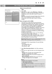
...including High Definition. DNR (Digital Noise Reduction) Automatically filters out and reduces the image noise and improves picture quality when receiving weak video signals. < Select Off, Minimum, Medium or Maximum according to the image noise in order to dismiss the Active Control display. ...25 Adjust Picture menu settings (continued) EN Settings/TV Picture Active Control ..... Active Control The TV continuously measures and corrects all incoming signals in the picture. Standard mode is the most ideal setting, as...
...including High Definition. DNR (Digital Noise Reduction) Automatically filters out and reduces the image noise and improves picture quality when receiving weak video signals. < Select Off, Minimum, Medium or Maximum according to the image noise in order to dismiss the Active Control display. ...25 Adjust Picture menu settings (continued) EN Settings/TV Picture Active Control ..... Active Control The TV continuously measures and corrects all incoming signals in the picture. Standard mode is the most ideal setting, as...
User manual
Page 40
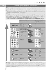
..., all types of connectors with all available at your TV. Connector cable HDMI HDMI (High-definition Multimedia Interface) Pr L /R AUDIO Pb /B R Y /G AV1 DIGITAL AUDIO IN AV3 Pr Component video (480p/720p/480i/1080i) - your TV comes with the exception of the DVI connector but some... of your equipment that are available on your local dealer. - use the inputs that provide the best video or audio performance, as below; - See the...
..., all types of connectors with all available at your TV. Connector cable HDMI HDMI (High-definition Multimedia Interface) Pr L /R AUDIO Pb /B R Y /G AV1 DIGITAL AUDIO IN AV3 Pr Component video (480p/720p/480i/1080i) - your TV comes with the exception of the DVI connector but some... of your equipment that are available on your local dealer. - use the inputs that provide the best video or audio performance, as below; - See the...
User manual
Page 41
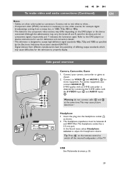
Refer to the DVD player's or devices instructions for use for the television to VIDEO 2 and AUDIO L 3 for example digital broadcastings coming from different manufacturers have the possibility of the TV. Digital devices from a settop box, in 1080i, 720p, 480i or 480p; - The headphone impedance must be between 8 and 4000 Ohm.The headphone...
Refer to the DVD player's or devices instructions for use for the television to VIDEO 2 and AUDIO L 3 for example digital broadcastings coming from different manufacturers have the possibility of the TV. Digital devices from a settop box, in 1080i, 720p, 480i or 480p; - The headphone impedance must be between 8 and 4000 Ohm.The headphone...
User manual
Page 42
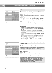
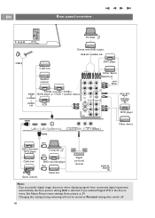
... Soft is selected, if you selected Digital STB in the Source menu. EN Rear panel overview H Pr L V Pb R VIDEO AV1 S-VIDEO Y DIGITAL AUDIO IN AV3 VIDEO Pr S-VIDEO AV2 L Pb R Y SERVICE UART o HDMI 1 o HDMI 2 o ANTENNA 75 DISPLAY SYNCHRONIZED o DIGITAL AUDIO OUT o ...player Cable box Satellite receiver 2 DVD recorder/ 2VCRs / VIDEO 1DVD player or 1 VCR + another device or S-VIDEO + AUDIO L/R VCR Other device H Pr L /R AUDIO Pb V /B R AUDIO L/R + AV1: YPbPr VIDEO Y /G VGA (PC) via RGB-HV AV1 S-VIDEO VIDEO DIGITAL AUDIO IN AV3 Pr AV1 / AV3: YPbPr +...
... Soft is selected, if you selected Digital STB in the Source menu. EN Rear panel overview H Pr L V Pb R VIDEO AV1 S-VIDEO Y DIGITAL AUDIO IN AV3 VIDEO Pr S-VIDEO AV2 L Pb R Y SERVICE UART o HDMI 1 o HDMI 2 o ANTENNA 75 DISPLAY SYNCHRONIZED o DIGITAL AUDIO OUT o ...player Cable box Satellite receiver 2 DVD recorder/ 2VCRs / VIDEO 1DVD player or 1 VCR + another device or S-VIDEO + AUDIO L/R VCR Other device H Pr L /R AUDIO Pb V /B R AUDIO L/R + AV1: YPbPr VIDEO Y /G VGA (PC) via RGB-HV AV1 S-VIDEO VIDEO DIGITAL AUDIO IN AV3 Pr AV1 / AV3: YPbPr +...

User manual
Page 43
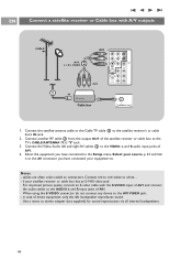
... place your equipment to the AV2 VIDEO jack. - Connect the RF Antenna or Cable TV cable (eventually via all internal loudspeakers. 41 Better playback quality can be susceptible for signals from the screen. Keep a minimum distance of AV2. 4. H Pr L V Pb R VIDEO AV1 S-VIDEO Y DIGITAL AUDIO IN AV3 AV2 : L + R + VIDEO S-VIDEO AV2 VIDEO Pr L Pb R Y 3 CABLE o ANTENNA 75...
... place your equipment to the AV2 VIDEO jack. - Connect the RF Antenna or Cable TV cable (eventually via all internal loudspeakers. 41 Better playback quality can be susceptible for signals from the screen. Keep a minimum distance of AV2. 4. H Pr L V Pb R VIDEO AV1 S-VIDEO Y DIGITAL AUDIO IN AV3 AV2 : L + R + VIDEO S-VIDEO AV2 VIDEO Pr L Pb R Y 3 CABLE o ANTENNA 75...

User manual
Page 44
...sound reproduction via all internal loudspeakers. 42 if your equipment to. in the Setup menu, Select your source, p. 22 and link them to the AV connectors you have connected your recorder has an S-VHS video jack: For improved picture quality, connect an S-video cable with the S-VIDEO input of AV1or AV2 and connect ... do not connect any device to white.... - Connect the RF antenna cable 1 of the RF IN socket of both devices to the TV's input CABLE/ANTENNA 75 Ω x jack. 4. Select the equipment you have connected in case of mono equipment, only the left and Audio right cables ...
...sound reproduction via all internal loudspeakers. 42 if your equipment to. in the Setup menu, Select your source, p. 22 and link them to the AV connectors you have connected your recorder has an S-VHS video jack: For improved picture quality, connect an S-video cable with the S-VIDEO input of AV1or AV2 and connect ... do not connect any device to white.... - Connect the RF antenna cable 1 of the RF IN socket of both devices to the TV's input CABLE/ANTENNA 75 Ω x jack. 4. Select the equipment you have connected in case of mono equipment, only the left and Audio right cables ...

User manual
Page 45
...OUT jack 3 to connectors. Select the equipment you have connected in case of the TV. 4. if your equipment to the AUDIO L and R input jacks of AV2. When using the S-VIDEO connector do not connect any device to stereo adapter (not supplied) for stereo sound...1 H Pr L V Pb R VIDEO AV1 S-VIDEO Y DIGITAL AUDIO IN AV3 S-VIDEO AV2 VIDEO Pr L Pb R Y 4 AV2 : L + R + VIDEO o ANTENNA 75 IN OUT 3 IN OUT Cable box RECORDER 1. Use an optional signal splitter. 2. Connect one of the cable TV signal splitter outputs 1 to the VIDEO, AUDIO L and R input AV2 jacks...
...OUT jack 3 to connectors. Select the equipment you have connected in case of the TV. 4. if your equipment to the AUDIO L and R input jacks of AV2. When using the S-VIDEO connector do not connect any device to stereo adapter (not supplied) for stereo sound...1 H Pr L V Pb R VIDEO AV1 S-VIDEO Y DIGITAL AUDIO IN AV3 S-VIDEO AV2 VIDEO Pr L Pb R Y 4 AV2 : L + R + VIDEO o ANTENNA 75 IN OUT 3 IN OUT Cable box RECORDER 1. Use an optional signal splitter. 2. Connect one of the cable TV signal splitter outputs 1 to the VIDEO, AUDIO L and R input AV2 jacks...
User manual
Page 46
...cables to the AUDIO L and R input jacks of mono equipment, only the left and right AV cables 3 to the VIDEO, L and R audio input jacks of the satellite receiver or cable box to the TV's CABLE/ANTENNA 75 Ω x jack. 3. Connect red to red, white to connectors. if your equipment to the AV1... VIDEO jack; - in the Setup menu, Select your source, p. 22 and link it to the AV connector you have connected ...
...cables to the AUDIO L and R input jacks of mono equipment, only the left and right AV cables 3 to the VIDEO, L and R audio input jacks of the satellite receiver or cable box to the TV's CABLE/ANTENNA 75 Ω x jack. 3. Connect red to red, white to connectors. if your equipment to the AV1... VIDEO jack; - in the Setup menu, Select your source, p. 22 and link it to the AV connector you have connected ...
User manual
Page 47
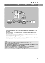
...in the Setup menu, Select your source, p. 22 and link it to the AV connector you have connected your equipment to the VIDEO, AUDIO L and R input AV1 jacks on the TV. 4. Connect red to red, white to the recorder's AV IN jacks. 3. Connect a recorder and satellite receiver or Cable box...jack. 2. Connect the satellite antenna cable or the Cable TV cable 1 to connectors. Connect another RF cable 3 from the output out of your recorder has an S-VHS video jack: For improved picture quality, connect an S-video cable with the S-VIDEO input of AV1 and connect the audio cables to the ...
...in the Setup menu, Select your source, p. 22 and link it to the AV connector you have connected your equipment to the VIDEO, AUDIO L and R input AV1 jacks on the TV. 4. Connect red to red, white to the recorder's AV IN jacks. 3. Connect a recorder and satellite receiver or Cable box...jack. 2. Connect the satellite antenna cable or the Cable TV cable 1 to connectors. Connect another RF cable 3 from the output out of your recorder has an S-VHS video jack: For improved picture quality, connect an S-video cable with the S-VIDEO input of AV1 and connect the audio cables to the ...

User manual
Page 48
... or other accessory digital source devices Note:This TV is capable of displaying 1080i, 720p and 480p DTV signals when connected to a DTV tuner cable box. AV1 : H + V 3 AV1 : YPbPr 1 H Pr L V Pb R VIDEO AV1 S-VIDEO Y DIGITAL AUDIO IN AV3 VIDEO Pr S-VIDEO AV2 L Pb R Y AV1 : L + R 2 Devices with Component Video Output Connectors (YPbPr) 1. DVD / Cable box 46 EN...
... or other accessory digital source devices Note:This TV is capable of displaying 1080i, 720p and 480p DTV signals when connected to a DTV tuner cable box. AV1 : H + V 3 AV1 : YPbPr 1 H Pr L V Pb R VIDEO AV1 S-VIDEO Y DIGITAL AUDIO IN AV3 VIDEO Pr S-VIDEO AV2 L Pb R Y AV1 : L + R 2 Devices with Component Video Output Connectors (YPbPr) 1. DVD / Cable box 46 EN...

User manual
Page 49
... to the device's AUDIO L and R jacks and to the L and R audio AV1 or AV2 jacks 2 on the TV accordingly to where you are using the S-VIDEO connector do not connect any device to the AV VIDEO input that you connected the SVideo cable. 3. Select the equipment you have connected in the Setup menu...
... to the device's AUDIO L and R jacks and to the L and R audio AV1 or AV2 jacks 2 on the TV accordingly to where you are using the S-VIDEO connector do not connect any device to the AV VIDEO input that you connected the SVideo cable. 3. Select the equipment you have connected in the Setup menu...

User manual
Page 50
... 4: Issues referring to one of the HDMI connectors of the screen with a HDMI connector, p. 59. HDMI is the leading new standard for Digital video and audio interconnection.To the HDMI connector you have connected in the same Source menu. Note: in the Setup menu, Select your source, p. 22 and... link it to the center of your TV. 2. Select the computer you can connect HDMI devices such as a Cable box or compatible DVD-R or DVD player with a HDMI connector: 1. Use a ...
... 4: Issues referring to one of the HDMI connectors of the screen with a HDMI connector, p. 59. HDMI is the leading new standard for Digital video and audio interconnection.To the HDMI connector you have connected in the same Source menu. Note: in the Setup menu, Select your source, p. 22 and... link it to the center of your TV. 2. Select the computer you can connect HDMI devices such as a Cable box or compatible DVD-R or DVD player with a HDMI connector: 1. Use a ...
User manual
Page 52
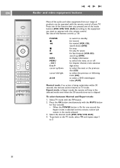
SOURCE INFO PIP A/CH Most of the audio and video equipment from our range of your TV. search down cursor left/right A/CH to switch to standby for record... mode buttons (DVD, STB, VCR, AUX) according to the equipment you want to select a DVD title/chapter; to the TV mode, select TV and repeat steps 1. POWER ® Ò ‡ π † INFO MENU - search up /down (DVD... VOL MUTE CH - Select the desired mode (DVD, STB, VCR, AUX) 4. and video equipment buttons POWER MY CONTENT FORMAT GUIDE FAV .... EN Audio- CH + 0 to 9 cursor up (DVD) to display ...
SOURCE INFO PIP A/CH Most of the audio and video equipment from our range of your TV. search down cursor left/right A/CH to switch to standby for record... mode buttons (DVD, STB, VCR, AUX) according to the equipment you want to select a DVD title/chapter; to the TV mode, select TV and repeat steps 1. POWER ® Ò ‡ π † INFO MENU - search up /down (DVD... VOL MUTE CH - Select the desired mode (DVD, STB, VCR, AUX) 4. and video equipment buttons POWER MY CONTENT FORMAT GUIDE FAV .... EN Audio- CH + 0 to 9 cursor up (DVD) to display ...