
Installation-Guide
Page 1
The model number is abbreviated in some descriptions in China Installation Guide Included Installation Instructions Network Camera Model No. PGQX1224YA Cs0313-1043 Printed in this manual for future use. WV-SW598 Before attempting to connect or operate this product, please read these instructions carefully and save this manual.
The model number is abbreviated in some descriptions in China Installation Guide Included Installation Instructions Network Camera Model No. PGQX1224YA Cs0313-1043 Printed in this manual for future use. WV-SW598 Before attempting to connect or operate this product, please read these instructions carefully and save this manual.

Installation-Guide
Page 3
... the user manuals...6 System requirements for a PC...7 Trademarks and registered trademarks...8 Copyright...8 Network security...8 Precautions...9 Precautions for installation...13 Major operating controls...15 Initialize the camera...17 Insert/remove an SD memory card*...18 Installations/Connections...20 Configure the network settings...31 Troubleshooting...33 Specifications...36 Standard accessories...39 Optional accessories...
... the user manuals...6 System requirements for a PC...7 Trademarks and registered trademarks...8 Copyright...8 Network security...8 Precautions...9 Precautions for installation...13 Major operating controls...15 Initialize the camera...17 Insert/remove an SD memory card*...18 Installations/Connections...20 Configure the network settings...31 Troubleshooting...33 Specifications...36 Standard accessories...39 Optional accessories...

Installation-Guide
Page 5
...It is necessary to install a web browser on a PC via a network. Disclaimer of warranty IN NO EVENT SHALL Panasonic System Networks Co., Ltd. Preface The network camera WV-SW598 is also necessary to configure the network settings of liability THIS PUBLICATION IS PROVIDED "AS IS" WITHOUT WARRANTY OF ANY KIND...COULD INCLUDE TECHNICAL INACCURACIES OR TYPOGRAPHICAL ERRORS. It is designed to a network (LAN) or the Internet, images and audio from the camera on the PC. CHANGES ARE ADDED TO THE INFORMATION HEREIN, AT ANY TIME, FOR THE IMPROVEMENTS OF THIS PUBLICATION AND/OR THE CORRESPONDING ...
...It is necessary to install a web browser on a PC via a network. Disclaimer of warranty IN NO EVENT SHALL Panasonic System Networks Co., Ltd. Preface The network camera WV-SW598 is also necessary to configure the network settings of liability THIS PUBLICATION IS PROVIDED "AS IS" WITHOUT WARRANTY OF ANY KIND...COULD INCLUDE TECHNICAL INACCURACIES OR TYPOGRAPHICAL ERRORS. It is designed to a network (LAN) or the Internet, images and audio from the camera on the PC. CHANGES ARE ADDED TO THE INFORMATION HEREIN, AT ANY TIME, FOR THE IMPROVEMENTS OF THIS PUBLICATION AND/OR THE CORRESPONDING ...
Installation-Guide
Page 6
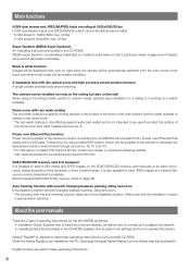
... & white function Images will be displayed clear even at night since the camera will be automatically switched from a web browser. Adobe® Reader® is required to read these operating instructions. 6 http://security.panasonic.com/pss/security/support/info.html SDXC/SDHC/SD memory card slot equipped ... card manually at an alarm occurrence, during the period of the dome cover from the Adobe web site and install it hard for the WV-SW598 as follows. • Installation Guide: Explains how to install and connect devices, as well as how to connect and configure the network....
... & white function Images will be displayed clear even at night since the camera will be automatically switched from a web browser. Adobe® Reader® is required to read these operating instructions. 6 http://security.panasonic.com/pss/security/support/info.html SDXC/SDHC/SD memory card slot equipped ... card manually at an alarm occurrence, during the period of the dome cover from the Adobe web site and install it hard for the WV-SW598 as follows. • Installation Guide: Explains how to install and connect devices, as well as how to connect and configure the network....

Installation-Guide
Page 8
... connected to a network that includes PCs, make sure to close the browser. • Change the administrator password periodically. • Do not install the camera in locations where the camera or the cables can be destroyed or damaged by restricting users to those who log in with an authorized user name and password...
... connected to a network that includes PCs, make sure to close the browser. • Change the administrator password periodically. • Do not install the camera in locations where the camera or the cables can be destroyed or damaged by restricting users to those who log in with an authorized user name and password...

Installation-Guide
Page 9
... in accidents. 9 Failure to the dealer. Precautions Refer installation work to observe this may cause fire or electric shock. Do not install or clean the camera, or touch this product, the power cable or the connected cables during thunder storms. Failure to observe this may cause a drop resulting in injury. Failure...
... in accidents. 9 Failure to the dealer. Precautions Refer installation work to observe this may cause fire or electric shock. Do not install or clean the camera, or touch this product, the power cable or the connected cables during thunder storms. Failure to observe this may cause a drop resulting in injury. Failure...

Installation-Guide
Page 10
...the dome cover with a cloth or other unwanted substances by installing it with PoE+ (IEEE802.3at compliant). Restart the product or refresh the camera position (position refresh) to the dome cover. To keep it is turned on. 10 Product disposal/transfer Data saved on this product may ...to replace the existing dome cover. Failure to have effective rain wash coating, a new dome cover must be moved inadvertently while cleaning the camera body. In this may cause damage or water exposure. Do not directly touch the surface of protection against snowfall by pouring or spraying ...
...the dome cover with a cloth or other unwanted substances by installing it with PoE+ (IEEE802.3at compliant). Restart the product or refresh the camera position (position refresh) to the dome cover. To keep it is turned on. 10 Product disposal/transfer Data saved on this product may ...to replace the existing dome cover. Failure to have effective rain wash coating, a new dome cover must be moved inadvertently while cleaning the camera body. In this may cause damage or water exposure. Do not directly touch the surface of protection against snowfall by pouring or spraying ...
Installation-Guide
Page 11
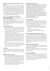
...AVC VIDEO. for 30 seconds or more in low temperatures below are just guides for a long period of time, the grease coating inside the camera has become deteriorated and this product. Contact your dealer for example, when it may be produced depending on the conditions of temperature, humidity, winds,...this product may not work properly or performance deterioration may take time to dehumidify. Periodically images on the screen appear to be distorted When the camera is installed in a location where it is subject to paste one of the labels onto the CD-ROM case. This phenomenon is a ...
...AVC VIDEO. for 30 seconds or more in low temperatures below are just guides for a long period of time, the grease coating inside the camera has become deteriorated and this product. Contact your dealer for example, when it may be produced depending on the conditions of temperature, humidity, winds,...this product may not work properly or performance deterioration may take time to dehumidify. Periodically images on the screen appear to be distorted When the camera is installed in a location where it is subject to paste one of the labels onto the CD-ROM case. This phenomenon is a ...

Installation-Guide
Page 12
However, when this product is set for the created schedule, the camera position will be corrected periodically. In this product to refer to perform the settings. Equipment classification and power source indication label Remove the main sunshield ...
However, when this product is set for the created schedule, the camera position will be corrected periodically. In this product to refer to perform the settings. Equipment classification and power source indication label Remove the main sunshield ...

Installation-Guide
Page 13
... case of the installation area. • Do not use wall mount bracket WV-Q122 (option). • When this product is a chance that the power cable is not connected to the camera. Precautions for installation Panasonic assumes no responsibility for Europe and other countries) power line. When the product... a power supply or remove a power cable. Remove the Protection Cover from the 120 V (for the installation area (such as a pendant mount camera. When the power cable of 1 m {3.28 feet} or more from the dome cover after the installation is no power switch. Power supply This...
... case of the installation area. • Do not use wall mount bracket WV-Q122 (option). • When this product is a chance that the power cable is not connected to the camera. Precautions for installation Panasonic assumes no responsibility for Europe and other countries) power line. When the product... a power supply or remove a power cable. Remove the Protection Cover from the 120 V (for the installation area (such as a pendant mount camera. When the power cable of 1 m {3.28 feet} or more from the dome cover after the installation is no power switch. Power supply This...

Installation-Guide
Page 17
... section (☞ page 19). The live indicator lights orange. IMPORTANT: • Do not turn on the power of the camera. 17 ization. Step 4 Turn off the power of the camera. (☞ Page 13) When the power is OFF. Be sure to return the INITIAL SET switch to write down the ...SD memory card" section (☞ page 18). Step 1 Pull out the water-resistant cap by following steps 1 - 3 of the "How to the default. The camera will start up and all the settings including the network settings will be complete when the live indicator will light orange → light off the...
... section (☞ page 19). The live indicator lights orange. IMPORTANT: • Do not turn on the power of the camera. 17 ization. Step 4 Turn off the power of the camera. (☞ Page 13) When the power is OFF. Be sure to return the INITIAL SET switch to write down the ...SD memory card" section (☞ page 18). Step 1 Pull out the water-resistant cap by following steps 1 - 3 of the "How to the default. The camera will start up and all the settings including the network settings will be complete when the live indicator will light orange → light off the...

Installation-Guide
Page 18
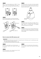
.... Main sunshield rear cover Step 2 Remove the locking screw of the sunshield. Step 1 Pull out the main sunshield rear cover on the rear of the camera by pressing the tab on the top of the water-resistant cap. SD memory card slot START INITIAL SET OFF ON LINK ACTSD Water-resistant...
.... Main sunshield rear cover Step 2 Remove the locking screw of the sunshield. Step 1 Pull out the main sunshield rear cover on the rear of the camera by pressing the tab on the top of the water-resistant cap. SD memory card slot START INITIAL SET OFF ON LINK ACTSD Water-resistant...
Installation-Guide
Page 19
...(Recommended tightening torque: 0.69 N·m {0.51 lbf·ft}) Locking screw Water-resistant cap Main sunshield rear cover Step 8 Turn on the power of the camera, and select "Use" for "SD memory card" on the [SD memory card] tab of the "Basic" page on the setup menu. (☞ Operating Instructions... the setup menu first. (☞ Operating Instructions (included in the CD-ROM)) Step 1 Remove the water-resistant cap by following steps 1 - 3 of the camera. Step 2 Push the SD memory card to release the lock. Step 5 Align "g" of the water-resistant cap to "OPEN h" of the "How to insert...
...(Recommended tightening torque: 0.69 N·m {0.51 lbf·ft}) Locking screw Water-resistant cap Main sunshield rear cover Step 8 Turn on the power of the camera, and select "Use" for "SD memory card" on the [SD memory card] tab of the "Basic" page on the setup menu. (☞ Operating Instructions... the setup menu first. (☞ Operating Instructions (included in the CD-ROM)) Step 1 Remove the water-resistant cap by following steps 1 - 3 of the camera. Step 2 Push the SD memory card to release the lock. Step 5 Align "g" of the water-resistant cap to "OPEN h" of the "How to insert...

Installation-Guide
Page 20
... mount bracket, use screws and anchors that are capable of supporting the combined weight of the camera (approx. 5 kg {11.02 lbs}) and the mount bracket. • When using the wall mount bracket (WV-Q122), use the 4 hexagon screws (M6) removed from the attachment pipe (accessory) and ...follow the above directions for the ceiling mount bracket and mount the camera using a custom-made ceiling mount bracket. • When mounting the camera to a wall, use the wall mount bracket WV-Q122 (option). * When using the wall mount bracket (WV-Q122), do not use the attachment pipe (accessory), use 4 ...
... mount bracket, use screws and anchors that are capable of supporting the combined weight of the camera (approx. 5 kg {11.02 lbs}) and the mount bracket. • When using the wall mount bracket (WV-Q122), use the 4 hexagon screws (M6) removed from the attachment pipe (accessory) and ...follow the above directions for the ceiling mount bracket and mount the camera using a custom-made ceiling mount bracket. • When mounting the camera to a wall, use the wall mount bracket WV-Q122 (option). * When using the wall mount bracket (WV-Q122), do not use the attachment pipe (accessory), use 4 ...

Installation-Guide
Page 21
... screws. * Special screw (Fixing screw): These screws are securing the housing base and the camera. How to detach the housing base Before attaching the camera to a custom-made mount bracket, detach the housing base and attachment pipe from the camera after the installation is complete. 21 Fixing screws (3 pcs.) Step 2 To separate the... housing base from the camera, turn the housing base to the direction of the arrow as illustrated. (Refer to the illustration in Step 1) Step 3 Remove the attachment pipe from the ...
... screws. * Special screw (Fixing screw): These screws are securing the housing base and the camera. How to detach the housing base Before attaching the camera to a custom-made mount bracket, detach the housing base and attachment pipe from the camera after the installation is complete. 21 Fixing screws (3 pcs.) Step 2 To separate the... housing base from the camera, turn the housing base to the direction of the arrow as illustrated. (Refer to the illustration in Step 1) Step 3 Remove the attachment pipe from the ...

Installation-Guide
Page 22
Refer to the "Precautions for installation" section before starting installation/connection, make sure that the camera can be mounted at the front of the bracket (WV-Q122) for details on a ceiling with a bracket. Take care of the direction to the installation surface on the ceiling by... Before starting installation/connection. (☞ Page 13) Step 1 Install the mounting bracket. The figure shows an example of the camera mounted on the installation procedure. Pass the cables through the wall mount bracket (WV-Q122) and then mount it to the installation guide of the bracket.
Refer to the "Precautions for installation" section before starting installation/connection, make sure that the camera can be mounted at the front of the bracket (WV-Q122) for details on a ceiling with a bracket. Take care of the direction to the installation surface on the ceiling by... Before starting installation/connection. (☞ Page 13) Step 1 Install the mounting bracket. The figure shows an example of the camera mounted on the installation procedure. Pass the cables through the wall mount bracket (WV-Q122) and then mount it to the installation guide of the bracket.

Installation-Guide
Page 23
... housing base to the mount bracket using the optional mounting bracket (WV-Q122), connect the safety wire near to the mount bracket 23...START" position. If not, turn the plate clockwise to the mount bracket. Plate spring Projection r Attach the camera to the bracket. Refer to the direction of the arrow as shown in the example below. Safety wire Wire... pcs.) attached to the wire hook section. * Special screw: These screws are hexagon screws. When attaching the camera to the housing base, the positioning pin on the upper side of the housing base shall be directed to the...
... housing base to the mount bracket using the optional mounting bracket (WV-Q122), connect the safety wire near to the mount bracket 23...START" position. If not, turn the plate clockwise to the mount bracket. Plate spring Projection r Attach the camera to the bracket. Refer to the direction of the arrow as shown in the example below. Safety wire Wire... pcs.) attached to the wire hook section. * Special screw: These screws are hexagon screws. When attaching the camera to the housing base, the positioning pin on the upper side of the housing base shall be directed to the...

Installation-Guide
Page 24
shields to the camera. Do not put an excessive weight that covers the housing base. Front and rear sunshields Wire Detach the hooks.... • Joint both sides of the front and rear sunshields are linked together with a wire. Front and rear sunshields Housing base Positioning pin Camera Protection Cover Step 5 Attach the front and rear sunshields (accessory) to detach the hooks. Then, turn the front and rear sunshields toward "g ... loss prevention, one side of front and rear sunshields. Housing base Align "h" to support only the weight of the camera when the camera falls.
shields to the camera. Do not put an excessive weight that covers the housing base. Front and rear sunshields Wire Detach the hooks.... • Joint both sides of the front and rear sunshields are linked together with a wire. Front and rear sunshields Housing base Positioning pin Camera Protection Cover Step 5 Attach the front and rear sunshields (accessory) to detach the hooks. Then, turn the front and rear sunshields toward "g ... loss prevention, one side of front and rear sunshields. Housing base Align "h" to support only the weight of the camera when the camera falls.

Installation-Guide
Page 25
Tape Camera Dome cover Protection Cover 25 Step 7 Fix the front and rear sunshields on the camera using the front/rear sunshield fixing screw (accessory). (Recommended tightening torque: 0.72 N·m {0.53 lbf·ft}) Front/rear sunshields xing screw Note: • When removing the front and rear sunshields, perform steps 5 - 7 in the reverse order. (☞ Pages 24 and 25) Step 8 After the installation is completed, remove the tape wrapped around the camera while holding the Protection Cover, and then take off the Protection Cover.
Tape Camera Dome cover Protection Cover 25 Step 7 Fix the front and rear sunshields on the camera using the front/rear sunshield fixing screw (accessory). (Recommended tightening torque: 0.72 N·m {0.53 lbf·ft}) Front/rear sunshields xing screw Note: • When removing the front and rear sunshields, perform steps 5 - 7 in the reverse order. (☞ Pages 24 and 25) Step 8 After the installation is completed, remove the tape wrapped around the camera while holding the Protection Cover, and then take off the Protection Cover.

Installation-Guide
Page 26
... plug-in the default settings of 24 V AC shall be insulated against 120 V AC (for U.S. IMPORTANT: • The power supply of the camera. Failure to observe this may cause fire, electric shock, injury, or damage to the product. • A READILY ACCESSIBLE DISCONNECT DEVICE SHALL BE INCORPORATED ... SUPPLY. If you want to change the video output setting to PAL, refer to the Operating Instructions on connected sections. • The network camera is discon- Connection Caution: • Before starting connections, make sure that the power connection (24 V AC power cord or LAN cable) ...
... plug-in the default settings of 24 V AC shall be insulated against 120 V AC (for U.S. IMPORTANT: • The power supply of the camera. Failure to observe this may cause fire, electric shock, injury, or damage to the product. • A READILY ACCESSIBLE DISCONNECT DEVICE SHALL BE INCORPORATED ... SUPPLY. If you want to change the video output setting to PAL, refer to the Operating Instructions on connected sections. • The network camera is discon- Connection Caution: • Before starting connections, make sure that the power connection (24 V AC power cord or LAN cable) ...


