Operating Instructions
Page 6
... malfunction. 8. herewith declares that produce heat. The camera could be caused on the fluorescent screen of electric shock. 4. Moisture can damage the camera and also create the danger of CRT. 12. Never aim the camera at the sun or other units that it will automatically reset its power. This... camera is hard to clean the camera when it happens frequently, check if there would be...
... malfunction. 8. herewith declares that produce heat. The camera could be caused on the fluorescent screen of electric shock. 4. Moisture can damage the camera and also create the danger of CRT. 12. Never aim the camera at the sun or other units that it will automatically reset its power. This... camera is hard to clean the camera when it happens frequently, check if there would be...

Operating Instructions
Page 9
...and White Mode 5 ■ Digital Flip 5 ■ Privacy Zone Function 5 ■ Patrol Function 5 ■ Camera Position Memory 5 ■ Motion Detection 5 ACCESORIES 5 OPTIONAL ACCESORIES 5 PRECAUTIONS 6 OPERATING PRECAUTIONS 7 CONSTRUCTION 10 INSTALLATION ...Unit Number (DIP Switch 1 13 ■ RS485 Communication Parameters (DIP Switch 1 14 CAMERA INSTALLATION 15 ■ Preparing the Camera and Decorative Cover for Side Cable Exit 15 ■ Installing the Camera 15 UNINSTALLING THE CAMERA 17 ■ Removing the Decorative Camera 17 ■ Uninstalling the Camera...
...and White Mode 5 ■ Digital Flip 5 ■ Privacy Zone Function 5 ■ Patrol Function 5 ■ Camera Position Memory 5 ■ Motion Detection 5 ACCESORIES 5 OPTIONAL ACCESORIES 5 PRECAUTIONS 6 OPERATING PRECAUTIONS 7 CONSTRUCTION 10 INSTALLATION ...Unit Number (DIP Switch 1 13 ■ RS485 Communication Parameters (DIP Switch 1 14 CAMERA INSTALLATION 15 ■ Preparing the Camera and Decorative Cover for Side Cable Exit 15 ■ Installing the Camera 15 UNINSTALLING THE CAMERA 17 ■ Removing the Decorative Camera 17 ■ Uninstalling the Camera...
Operating Instructions
Page 12
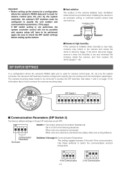
...information about how to access the DIP switches. When only one camera is used for camera control (pan, tilt, etc.) by the system controller, the camera's DIP switches must be configured to specify the unit number and communication parameters. Communication Parameters Terminator Switches 2 through ... Important: • Before setting up the camera for a configuration where the camera's RS485 data port is used for camera control (pan, tilt, etc.) by the system controller, the camera's DIP switches must be configured to specify the unit number and communication parameters. (This page) ...
...information about how to access the DIP switches. When only one camera is used for camera control (pan, tilt, etc.) by the system controller, the camera's DIP switches must be configured to specify the unit number and communication parameters. Communication Parameters Terminator Switches 2 through ... Important: • Before setting up the camera for a configuration where the camera's RS485 data port is used for camera control (pan, tilt, etc.) by the system controller, the camera's DIP switches must be configured to specify the unit number and communication parameters. (This page) ...
Operating Instructions
Page 14
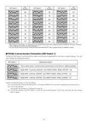
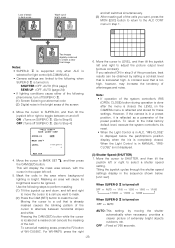
For details about configuring this setting, see step 2 and page 20. * Turning on power when this setting. (1) Turn off the camera, use this setting is selected causes the RS485 SET UP menu to appear during the initialization routine. ■ RS485 Communication Parameters (DIP ...the setting you configured in step (1). (3) Turn off the camera and use DIP Switch 1 to set the unit number (pages 13 and 14), and then turn the camera back on the camera. DIP Switch 1 Unit Number DIP Switch 1 Unit Number DIP Switch 1 Unit Number ON 12345678 ON 12345678 ON 12345678 ON 12345678 ON 12345678...
For details about configuring this setting, see step 2 and page 20. * Turning on power when this setting. (1) Turn off the camera, use this setting is selected causes the RS485 SET UP menu to appear during the initialization routine. ■ RS485 Communication Parameters (DIP ...the setting you configured in step (1). (3) Turn off the camera and use DIP Switch 1 to set the unit number (pages 13 and 14), and then turn the camera back on the camera. DIP Switch 1 Unit Number DIP Switch 1 Unit Number DIP Switch 1 Unit Number ON 12345678 ON 12345678 ON 12345678 ON 12345678 ON 12345678...

Operating Instructions
Page 15
... for information about how to remove the camera mounting base. * Prevent the dome cover from the side. Affix the camera mounting base onto the ceiling. The camera mounting base needs to be prepared as a template, mark the locations of pliers. 2. Rotate the camera base unit in a place where it . -15...- Screws (M4, available separately) Dust Protection Sheet (comes with a pair of the four mounting holes on the camera and then remove it will not become lost. Rotate 15° ...
... for information about how to remove the camera mounting base. * Prevent the dome cover from the side. Affix the camera mounting base onto the ceiling. The camera mounting base needs to be prepared as a template, mark the locations of pliers. 2. Rotate the camera base unit in a place where it . -15...- Screws (M4, available separately) Dust Protection Sheet (comes with a pair of the four mounting holes on the camera and then remove it will not become lost. Rotate 15° ...

Operating Instructions
Page 17
... remove it will not become lost. 2. Rotate the camera in a place where it . 15° Rotate Camera Camera Mounting Base 3. Back Unhook Fix securely Press Fix securely Press ■ Uninstalling the Camera The camera and its base unit are secured by the arrow and remove it . 1. Remove the camera from the mounting base. -17- Failure to do...
... remove it will not become lost. 2. Rotate the camera in a place where it . 15° Rotate Camera Camera Mounting Base 3. Back Unhook Fix securely Press Fix securely Press ■ Uninstalling the Camera The camera and its base unit are secured by the arrow and remove it . 1. Remove the camera from the mounting base. -17- Failure to do...
Operating Instructions
Page 19
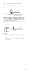
...{{00.1.1"}"} UUpp A Insert WWiriere IInnsseertrtththeewwireireunutniltAil Apopsoitisointion aannddcclalammppthtehecocnotanctatsc. After clamping the contacts, push them into the proper holes in the accessory connector of this camera until ascertaining that the unit is a one-time procedure. Up Wire Contact Cautions: • Shrinking the cable-entry seal is functioning. • CONNECT THIS TO 24 V AC CLASS...
...{{00.1.1"}"} UUpp A Insert WWiriere IInnsseertrtththeewwireireunutniltAil Apopsoitisointion aannddcclalammppthtehecocnotanctatsc. After clamping the contacts, push them into the proper holes in the accessory connector of this camera until ascertaining that the unit is a one-time procedure. Up Wire Contact Cautions: • Shrinking the cable-entry seal is functioning. • CONNECT THIS TO 24 V AC CLASS...
Operating Instructions
Page 20
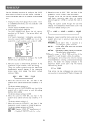
...to a request by the system controller. POLLING : Sends alarm data in the sequence shown below . (unit: ms) The factory default setting is sent. This is the time that the camera should wait before resending data when no receive acknowledgement (ACK) is returned after data is OFF. Tilting the...to BAUD RATE, and then tilt the joystick left or right to control the camera (pan, tilt, etc.) via the camera's data port. 1. Move the cursor to DATA BIT, and then tilt the joystick left or right to select a unit number (1 to select a data bit setting (7 or 8). If DIP Switch 1...
...to a request by the system controller. POLLING : Sends alarm data in the sequence shown below . (unit: ms) The factory default setting is sent. This is the time that the camera should wait before resending data when no receive acknowledgement (ACK) is returned after data is OFF. Tilting the...to BAUD RATE, and then tilt the joystick left or right to control the camera (pan, tilt, etc.) via the camera's data port. 1. Move the cursor to DATA BIT, and then tilt the joystick left or right to select a unit number (1 to select a data bit setting (7 or 8). If DIP Switch 1...
Operating Instructions
Page 23
...simultaneously. (3) After masking all masking areas, press the F2 button of bright areas ... However, if the camera is closed . To return to the initial factory default level, execute the system controller's iris reset. ...SET LEVEL ••••I•••• - + 6. Mask the cells in ALC, "IRIS-CLOSE" is displayed below . (unit: sec) When SUPER-D 3 is turned off OFF ↔ AUTO ↔ 1/100 ↔ 1/250 ↔ 1/500 ↔ 1/1000... SET O, and then press the CAM (SET) button. For WV-RM70, press the right (3) Shutter Speed (SHUTTER) 1. Wash out of...
...simultaneously. (3) After masking all masking areas, press the F2 button of bright areas ... However, if the camera is closed . To return to the initial factory default level, execute the system controller's iris reset. ...SET LEVEL ••••I•••• - + 6. Mask the cells in ALC, "IRIS-CLOSE" is displayed below . (unit: sec) When SUPER-D 3 is turned off OFF ↔ AUTO ↔ 1/100 ↔ 1/250 ↔ 1/500 ↔ 1/1000... SET O, and then press the CAM (SET) button. For WV-RM70, press the right (3) Shutter Speed (SHUTTER) 1. Wash out of...
Operating Instructions
Page 29
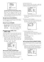
... the one you are currently configuring. Scene files are managed using scene file numbers from 1 through the stop time display in the sequence shown below. (unit: sec, min) 2S ↔ 3S ↔ 5S ↔ 10S ↔ 30S ↔ 1MIN 4MIN ↔ 3MIN ↔ 2MIN PRESET NO...the various preset positions for details on the setting method. PRESET NO. 1* 0123456789 ABCDEFGHIJKLM NOPQRSTUVWXYZ SPACE COPY POSI RET RESET DOOR............ See camera settings for the sequence and sort operations (page 30, 31). 1. Tilting the joystick cycles through 10, and can be selected when ...
... the one you are currently configuring. Scene files are managed using scene file numbers from 1 through the stop time display in the sequence shown below. (unit: sec, min) 2S ↔ 3S ↔ 5S ↔ 10S ↔ 30S ↔ 1MIN 4MIN ↔ 3MIN ↔ 2MIN PRESET NO...the various preset positions for details on the setting method. PRESET NO. 1* 0123456789 ABCDEFGHIJKLM NOPQRSTUVWXYZ SPACE COPY POSI RET RESET DOOR............ See camera settings for the sequence and sort operations (page 30, 31). 1. Tilting the joystick cycles through 10, and can be selected when ...

Operating Instructions
Page 30
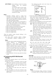
Pressing the HOME button of time elapses without any setting other than OFF in the sequence shown below. (unit: sec, min) OFF ↔ 1S ↔ 2S ↔ 3S 10S ↔ 20S ↔ 30S ↔ 40S 60MIN 50S 30MIN ↔ 20MIN ↔ 10MIN ↔...: Activates the patrol function when the trigger time elapses. Use the following procedure to select a self return trigger setting. Following that, after a set time, the camera returns to the home position and starts to DEL, and then press the CAM (SET) button. ● Deleting a Preset Position (DEL) 1. Move the cursor...
Pressing the HOME button of time elapses without any setting other than OFF in the sequence shown below. (unit: sec, min) OFF ↔ 1S ↔ 2S ↔ 3S 10S ↔ 20S ↔ 30S ↔ 40S 60MIN 50S 30MIN ↔ 20MIN ↔ 10MIN ↔...: Activates the patrol function when the trigger time elapses. Use the following procedure to select a self return trigger setting. Following that, after a set time, the camera returns to the home position and starts to DEL, and then press the CAM (SET) button. ● Deleting a Preset Position (DEL) 1. Move the cursor...
Operating Instructions
Page 31
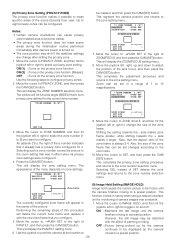
.... (1) Move the cursor to POSITION, press the CAM (SET) button, and then move the cursor to START. (2) Use the joystick to move the camera to select the start point and the end point. Perform the following conditions. Shifting the setting towards the "H" (right) side increases the speed, while shifting... tilt the joystick left or right to the desired PAN end point, and then press the CAM (SET) button. Move the cursor to directly below . (unit: sec) 0S ↔ 1S ↔ 2S ↔ 3S ↔ 5S ↔ 10S ↔ 20S ↔ 30S 5. AUTO TRACK : Auto tracking is operating and ...
.... (1) Move the cursor to POSITION, press the CAM (SET) button, and then move the cursor to START. (2) Use the joystick to move the camera to select the start point and the end point. Perform the following conditions. Shifting the setting towards the "H" (right) side increases the speed, while shifting... tilt the joystick left or right to the desired PAN end point, and then press the CAM (SET) button. Move the cursor to directly below . (unit: sec) 0S ↔ 1S ↔ 2S ↔ 3S ↔ 5S ↔ 10S ↔ 20S ↔ 30S 5. AUTO TRACK : Auto tracking is operating and ...
Operating Instructions
Page 32
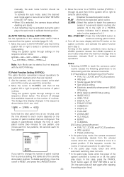
...joystick cycles through settings in the sequence shown below. Move the cursor to a PATROL number (PATROL 1 through settings in the sequence shown below . (unit: sec, min) 1(2MIN) ↔ 2(1MIN) ↔ 4(30S) Note that the total patrol time is two minutes, and the time allowed ...Auto Mode can be cancelled. The storage time display changes in the sequence shown below . Notes: • Selecting LEARN to teach the camera a patrol routine causes the following parameters to be activated during a LEARN operation causes the LEARN operation to remember. 2. It also ends ...
...joystick cycles through settings in the sequence shown below. Move the cursor to a PATROL number (PATROL 1 through settings in the sequence shown below . (unit: sec, min) 1(2MIN) ↔ 2(1MIN) ↔ 4(30S) Note that the total patrol time is two minutes, and the time allowed ...Auto Mode can be cancelled. The storage time display changes in the sequence shown below . Notes: • Selecting LEARN to teach the camera a patrol routine causes the following parameters to be activated during a LEARN operation causes the LEARN operation to remember. 2. It also ends ...
Operating Instructions
Page 33
...the privacy zone function. (Mosaic) OFF : Turns off . Zoom can be set in handy when using a network interface unit for the current zone number. **ZONE NUMBER 1 /8** be displayed as the camera 6. Press the CAM (SET) button. The appearance of 1 to 10 magnifications. **ZONE NUMBER 3 /8** PAN/TILT ...completes the privacy zone setting procedure and returns to configure. PAN/TILT, and then press the CAM (SET) button. Notes: • Certain camera orientations can be distorted 5. ON (2) : Turns on the privacy zone function. Move the cursor to ZONE NUMBER, and then tilt the ...
...the privacy zone function. (Mosaic) OFF : Turns off . Zoom can be set in handy when using a network interface unit for the current zone number. **ZONE NUMBER 1 /8** be displayed as the camera 6. Press the CAM (SET) button. The appearance of 1 to 10 magnifications. **ZONE NUMBER 3 /8** PAN/TILT ...completes the privacy zone setting procedure and returns to configure. PAN/TILT, and then press the CAM (SET) button. Notes: • Certain camera orientations can be distorted 5. ON (2) : Turns on the privacy zone function. Move the cursor to ZONE NUMBER, and then tilt the ...
Operating Instructions
Page 37
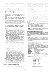
... joystick cycles through the setting display in the sequence shown below . (unit: sec, min) If you set the SELF RETURN setting to the alarm terminal of about 0.2 second from the point that the camera detects change (movement) in the image during the blanking period. Tilting the... joystick cycles through the setting display in the sequence shown below . (unit: sec) 2S ↔ 5S ↔ 10S ↔ 30S 7. connector....
... joystick cycles through the setting display in the sequence shown below . (unit: sec, min) If you set the SELF RETURN setting to the alarm terminal of about 0.2 second from the point that the camera detects change (movement) in the image during the blanking period. Tilting the... joystick cycles through the setting display in the sequence shown below . (unit: sec) 2S ↔ 5S ↔ 10S ↔ 30S 7. connector....
Operating Instructions
Page 38
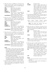
...the joystick left or right to 4 (S) if you selected ALARM in steps 2 through 5, above. OFF : No alarm signal output Notes: • The camera ignores alarm inputs during manual operation. • Turn off . This setting turns alarm controls whether an alarm is received. ALARM IN4 can be performed over... then tilt the joystick left and right to specify the alarm signal output time. To use the camera with BW. AUX1 : Output a contact close signal when AUX2 input is in the sequence shown below. (unit: ms) 100 MS ↔ 200 MS ↔ 1000 MS ↔ 2000 MS ↔ 4000...
...the joystick left or right to 4 (S) if you selected ALARM in steps 2 through 5, above. OFF : No alarm signal output Notes: • The camera ignores alarm inputs during manual operation. • Turn off . This setting turns alarm controls whether an alarm is received. ALARM IN4 can be performed over... then tilt the joystick left and right to specify the alarm signal output time. To use the camera with BW. AUX1 : Output a contact close signal when AUX2 input is in the sequence shown below. (unit: ms) 100 MS ↔ 200 MS ↔ 1000 MS ↔ 2000 MS ↔ 4000...

