Installation Guide
Page 1
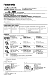
...L (1 pc.) Order No. All steps are omitted from a PC. • BL-C230A only: Refer to the included Setup Guide for VIERA Connection for indicator meaning. *3 BL-C230A only © Panasonic System Networks Co., Ltd. 2009 PNQX2272ZA KK1009CQ0 Washer S (2 pcs.) Order No. ... a LAN cable (CAT-5 straight cable) - XWG4F16VW Used when securing the safety wire to the wall. Panasonic Network Camera Website: http://panasonic.net/pcc/ipcam/ BL-C230 Model No. (Wireless/Wired Type) Model number suffixes ("A", "CE", and "E") are explained in this document, unless necessary. Confirm...
...L (1 pc.) Order No. All steps are omitted from a PC. • BL-C230A only: Refer to the included Setup Guide for VIERA Connection for indicator meaning. *3 BL-C230A only © Panasonic System Networks Co., Ltd. 2009 PNQX2272ZA KK1009CQ0 Washer S (2 pcs.) Order No. ... a LAN cable (CAT-5 straight cable) - XWG4F16VW Used when securing the safety wire to the wall. Panasonic Network Camera Website: http://panasonic.net/pcc/ipcam/ BL-C230 Model No. (Wireless/Wired Type) Model number suffixes ("A", "CE", and "E") are explained in this document, unless necessary. Confirm...
Installation Guide
Page 2
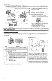
...your router or to the Panasonic Network Camera website (http://panasonic.net/pcc/ipcam/) for more information. 1 Confirm that the indicator turns green after about 1 minute. The camera can be changed (see 7.4 Controlling the External Output Terminal (BL-C230 Only) in the Operating Instructions... IN1 2 3 IN2 4 5 OUT 6 Description External sensor input. External device control output. WIRELESS/ WIRED switch 4 Plug the AC adaptor into the power outlet. • Confirm that the WIRELESS/WIRED switch on the included CD-ROM. This is connected to the camera's output terminals cannot...
...your router or to the Panasonic Network Camera website (http://panasonic.net/pcc/ipcam/) for more information. 1 Confirm that the indicator turns green after about 1 minute. The camera can be changed (see 7.4 Controlling the External Output Terminal (BL-C230 Only) in the Operating Instructions... IN1 2 3 IN2 4 5 OUT 6 Description External sensor input. External device control output. WIRELESS/ WIRED switch 4 Plug the AC adaptor into the power outlet. • Confirm that the WIRELESS/WIRED switch on the included CD-ROM. This is connected to the camera's output terminals cannot...
Installation Guide
Page 3
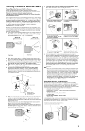
... between objects in the following areas. Because the detection range is no temperature difference between the camera and the wireless router is aimed at http://panasonic.net/pcc/support/netwkcam/ for security or surveillance. As shown in front of the camera's sensor and the surrounding ...objects that you are not designed to make inaccurate detections. Therefore, even if the distance between the camera and the wireless router. Refer to the Panasonic Network Camera website at an area outside of the sensor (see Section 2 Using Triggers to Buffer and Transfer Images in...
... between objects in the following areas. Because the detection range is no temperature difference between the camera and the wireless router is aimed at http://panasonic.net/pcc/support/netwkcam/ for security or surveillance. As shown in front of the camera's sensor and the surrounding ...objects that you are not designed to make inaccurate detections. Therefore, even if the distance between the camera and the wireless router. Refer to the Panasonic Network Camera website at an area outside of the sensor (see Section 2 Using Triggers to Buffer and Transfer Images in...

