

AJHVF21G User Guide
Page 1
... 2-inch Electronic HD View Finder/2-Zoll Elektronischer HD-Sucher HD Viseur électronique de 2 pouce/HD Mirino Elettronico da 2 pollici HD Visor Electrónico de 2 pulgadas AJ- AJ- ENGLISH DEUTSCH Operating Instructions/Bedienungsanleitung Mode d'emploi/Istruzioni per riferimenti futuri. G FRANÇAIS ITALIANO ESPAÑOL Before operating this product, please read the instructions carefully and save this manual for future use. G Model No...
... 2-inch Electronic HD View Finder/2-Zoll Elektronischer HD-Sucher HD Viseur électronique de 2 pouce/HD Mirino Elettronico da 2 pollici HD Visor Electrónico de 2 pulgadas AJ- AJ- ENGLISH DEUTSCH Operating Instructions/Bedienungsanleitung Mode d'emploi/Istruzioni per riferimenti futuri. G FRANÇAIS ITALIANO ESPAÑOL Before operating this product, please read the instructions carefully and save this manual for future use. G Model No...

AJHVF21G User Guide
Page 2
... equipment generates, uses, and can radiate radio frequency energy, and if not installed and used in the video and audio signals. Operating precaution Operation near any interference received, including interference that may cause harmful interference to radio communications. O Do not point the eyepiece directly at his own expense. Caution: O The interior of this device must use only shielded interface cables when connecting to external units. Operation is subject to...
... equipment generates, uses, and can radiate radio frequency energy, and if not installed and used in the video and audio signals. Operating precaution Operation near any interference received, including interference that may cause harmful interference to radio communications. O Do not point the eyepiece directly at his own expense. Caution: O The interior of this device must use only shielded interface cables when connecting to external units. Operation is subject to...

AJHVF21G User Guide
Page 3
... Functions 3 For cameras compatible with the standard slide rail 6 Mounting the Viewfinder 6 Adjusting the viewfinder's left-right position 7 Adjusting the viewfinder's front-back position 7 Detaching the Viewfinder 8 For cameras compatible with the mounting unit 9 Mounting the Viewfinder 10 Detaching the Viewfinder 10 Position Adjustment 11 Diopter Adjustment 12 Screen Adjustment 12 Detaching the Eyepiece 13 Mounting the Microphone 14 Specifications 15 E-2 For disposal or recycling information, please contact...
... Functions 3 For cameras compatible with the standard slide rail 6 Mounting the Viewfinder 6 Adjusting the viewfinder's left-right position 7 Adjusting the viewfinder's front-back position 7 Detaching the Viewfinder 8 For cameras compatible with the mounting unit 9 Mounting the Viewfinder 10 Detaching the Viewfinder 10 Position Adjustment 11 Diopter Adjustment 12 Screen Adjustment 12 Detaching the Eyepiece 13 Mounting the Microphone 14 Specifications 15 E-2 For disposal or recycling information, please contact...

AJHVF21G User Guide
Page 4
... and 1080/50 fields depending on the control signal from your eye. The details of the display, such as the type of the camera for details. 2 TALLY Switch Controls the front tally lamp. LOW: Makes the front tally lamp dimmer. OThe large eyepiece aperture makes it possible to the instruction manual of zebra pattern, will differ depending on...
... and 1080/50 fields depending on the control signal from your eye. The details of the display, such as the type of the camera for details. 2 TALLY Switch Controls the front tally lamp. LOW: Makes the front tally lamp dimmer. OThe large eyepiece aperture makes it possible to the instruction manual of zebra pattern, will differ depending on...

AJHVF21G User Guide
Page 5
... LOW. Connection Plug < Lock Ring = Microphone Holder > Slide rail E-4 Also, flashes on the output signal of the camera. 4 CONTRAST Knob Adjusts the contrast of the screen inside the viewfinder. The back tally lamp is hidden when the lever is in the OFF position. : Diopter Adjustment Ring Adjust this control has no effect on the output signal of the camera. 6 Front Tally Lamp Lights when the camera is shooting...
... LOW. Connection Plug < Lock Ring = Microphone Holder > Slide rail E-4 Also, flashes on the output signal of the camera. 4 CONTRAST Knob Adjusts the contrast of the screen inside the viewfinder. The back tally lamp is hidden when the lever is in the OFF position. : Diopter Adjustment Ring Adjust this control has no effect on the output signal of the camera. 6 Front Tally Lamp Lights when the camera is shooting...

AJHVF21G User Guide
Page 6
TALLY / REC BATT SAVE E-5 Refer to the instruction manual of the camera for details. Parts and Their Functions Internal LEDs The lamp and picture tube indications will differ depending on the camera used with the viewfinder.
TALLY / REC BATT SAVE E-5 Refer to the instruction manual of the camera for details. Parts and Their Functions Internal LEDs The lamp and picture tube indications will differ depending on the camera used with the viewfinder.

AJHVF21G User Guide
Page 7
... the POWER switch of the arrow. Insert the plug into the connection jack. Tighten the viewfinder left -right position anchoring ring. 4. E-6 Be sure to insert the plug all the way into the connection jack of the viewfinder. Viewfinder stopper 5. Loosen the viewfinder left -right position anchoring ring. ENGLISH For cameras compatible with the standard slide rail The following cameras support the standard...
... the POWER switch of the arrow. Insert the plug into the connection jack. Tighten the viewfinder left -right position anchoring ring. 4. E-6 Be sure to insert the plug all the way into the connection jack of the viewfinder. Viewfinder stopper 5. Loosen the viewfinder left -right position anchoring ring. ENGLISH For cameras compatible with the standard slide rail The following cameras support the standard...

AJHVF21G User Guide
Page 8
... viewfinder's front-back position 1. E-7 Slide the viewfinder to the front or back, and adjust it to a position that allows easy viewing. Viewfinder front-back position anchoring ring 3. Tighten the viewfinder front-back position anchoring ring. Loosen the viewfinder left -right...back position anchoring ring. 2. Tighten the viewfinder left -right position 1. Slide the viewfinder to the left or right, and adjust it to a position that allows easy viewing. For cameras compatible with the standard slide rail Adjusting the viewfinder's left -right position anchoring ring.
... viewfinder's front-back position 1. E-7 Slide the viewfinder to the front or back, and adjust it to a position that allows easy viewing. Viewfinder front-back position anchoring ring 3. Tighten the viewfinder front-back position anchoring ring. Loosen the viewfinder left -right...back position anchoring ring. 2. Tighten the viewfinder left -right position 1. Slide the viewfinder to the left or right, and adjust it to a position that allows easy viewing. For cameras compatible with the standard slide rail Adjusting the viewfinder's left -right position anchoring ring.

AJHVF21G User Guide
Page 9
Tighten the ring. E-8 While pulling up the viewfinder stopper, remove the viewfinder by sliding it in the direction of the camera is "OFF". 2. Release the viewfinder cable and mic cable from the cable clamps, and disconnect the cables. ENGLISH For cameras compatible with the standard slide rail Detaching the Viewfinder 1. Loosen the viewfinder left-right position anchoring ring. 3. Viewfinder stopper 4. Confirm that the POWER switch of the arrow.
Tighten the ring. E-8 While pulling up the viewfinder stopper, remove the viewfinder by sliding it in the direction of the camera is "OFF". 2. Release the viewfinder cable and mic cable from the cable clamps, and disconnect the cables. ENGLISH For cameras compatible with the standard slide rail Detaching the Viewfinder 1. Loosen the viewfinder left-right position anchoring ring. 3. Viewfinder stopper 4. Confirm that the POWER switch of the arrow.

AJHVF21G User Guide
Page 10
... the two screws, then detach the standard slide rail. Screws Mounting unit E-9 For cameras compatible with the mounting unit The standard slide rail can be removed and replaced with the two screws. Secure the mounting unit in mind that this unit is a repair part. The following cameras support the mounting unit. Viewfinder model number AJ-HVF21G AJ-HVF27BG Camera model number AJ-HDC20A AJ-HDC20AP AJ-HDC27F AJ-HDC27FP AJ-HDC27FE...
... the two screws, then detach the standard slide rail. Screws Mounting unit E-9 For cameras compatible with the mounting unit The standard slide rail can be removed and replaced with the two screws. Secure the mounting unit in mind that this unit is a repair part. The following cameras support the mounting unit. Viewfinder model number AJ-HVF21G AJ-HVF27BG Camera model number AJ-HDC20A AJ-HDC20AP AJ-HDC27F AJ-HDC27FP AJ-HDC27FE...

AJHVF21G User Guide
Page 11
.... The viewfinder may not detach smoothly with the mounting unit Mounting the Viewfinder 1. Confirm that the POWER switch of the camera is "OFF". 2. Loosen the stopper screw and detach the viewfinder by pulling it straight up. Use both hands to insert the plug all the way into the connection jack. 3. ENGLISH For cameras compatible with one hand, resulting in damage to the...
.... The viewfinder may not detach smoothly with the mounting unit Mounting the Viewfinder 1. Confirm that the POWER switch of the camera is "OFF". 2. Loosen the stopper screw and detach the viewfinder by pulling it straight up. Use both hands to insert the plug all the way into the connection jack. 3. ENGLISH For cameras compatible with one hand, resulting in damage to the...

AJHVF21G User Guide
Page 12
E-11 Lift up the viewfinder forward-backward/left -right position clamp lever to disengage the lock. Lever Viewfinder 2. Return the viewfinder forward-backward/left -right position clamp lever to the locked position. Adjust the position of the viewfinder by moving it forward, backward, left -right position clamp lever. 3. For cameras compatible with the mounting unit Position Adjustment 1. Loosen the viewfinder forward-backward/left or right. 4.
E-11 Lift up the viewfinder forward-backward/left -right position clamp lever to disengage the lock. Lever Viewfinder 2. Return the viewfinder forward-backward/left -right position clamp lever to the locked position. Adjust the position of the viewfinder by moving it forward, backward, left -right position clamp lever. 3. For cameras compatible with the mounting unit Position Adjustment 1. Loosen the viewfinder forward-backward/left or right. 4.

AJHVF21G User Guide
Page 13
... control CONTRAST control BRIGHT control 1. E-12 Diopter Adjustment 1. Turn the diopter adjustment ring to adjust the picture brightness and contrast. Turning the PEAKING control makes the picture appear sharper. A sharper picture facilitates focusing the lens. Diopter Adjustment Ring ENGLISH Screen Adjustment Adjust the condition of the camera to "BAR". 3. Set the OUTPUT switch of the viewfinder screen. Brightness: Adjust the BRIGHT control. A picture will appear in the viewfinder. 2. Set the POWER switch of the camera to "ON". 2. Contour: Adjust...
... control CONTRAST control BRIGHT control 1. E-12 Diopter Adjustment 1. Turn the diopter adjustment ring to adjust the picture brightness and contrast. Turning the PEAKING control makes the picture appear sharper. A sharper picture facilitates focusing the lens. Diopter Adjustment Ring ENGLISH Screen Adjustment Adjust the condition of the camera to "BAR". 3. Set the OUTPUT switch of the viewfinder screen. Brightness: Adjust the BRIGHT control. A picture will appear in the viewfinder. 2. Set the POWER switch of the camera to "ON". 2. Contour: Adjust...

AJHVF21G User Guide
Page 14
... has adhered to line up the alignment marks on the lock ring and viewfinder barrel. Alignment marks Eyepiece Lock ring 2. Turn the lock ring clockwise as far as it . Turn the lock ring as far as possible in the clockwise and counterclockwise directions to the mirror should be blown away with a blower,... etc. 1. Line up the alignment marks on the lock ring and the viewfinder barrel and slide the eyepiece back into place. 2. E-13 Detach the eyepiece. Detaching the Eyepiece If dust has adhered to the CRT screen ...
... has adhered to line up the alignment marks on the lock ring and viewfinder barrel. Alignment marks Eyepiece Lock ring 2. Turn the lock ring clockwise as far as it . Turn the lock ring as far as possible in the clockwise and counterclockwise directions to the mirror should be blown away with a blower,... etc. 1. Line up the alignment marks on the lock ring and the viewfinder barrel and slide the eyepiece back into place. 2. E-13 Detach the eyepiece. Detaching the Eyepiece If dust has adhered to the CRT screen ...

AJHVF21G User Guide
Page 15
Viewfinder 2. MIC IN jack E-14 Mount the microphone. Microphone holder 3. Plug the microphone connector cable into the MIC IN jack. ENGLISH Mounting the Microphone Follow the steps below to install the AJ-MC700P or the AJ-MC900G microphone kit (sold separately). 1. Open the microphone holder.
Viewfinder 2. MIC IN jack E-14 Mount the microphone. Microphone holder 3. Plug the microphone connector cable into the MIC IN jack. ENGLISH Mounting the Microphone Follow the steps below to install the AJ-MC700P or the AJ-MC900G microphone kit (sold separately). 1. Open the microphone holder.

AJHVF21G User Guide
Page 16
Specifications Power supply: DC 12 V (supplied by camera) Power consumption: 3.8 W (AJ-HVF21G) 4.1 W (AJ-HVF27BG) indicates safety information. Specifications are subject to 104°F) Allowable humidity range: 85% or less (no condensation) External dimensions (WaHaD): 240 mma80 mma206 mm (9 1/2 inchesa3 3/16 inchesa8 1/8 inches) Weight: 750 g (1.65 lb) Weight and dimentions when shown are approximately. E-15 Picture tube: 2-inch high-resolution monochrome picture tube Image...
Specifications Power supply: DC 12 V (supplied by camera) Power consumption: 3.8 W (AJ-HVF21G) 4.1 W (AJ-HVF27BG) indicates safety information. Specifications are subject to 104°F) Allowable humidity range: 85% or less (no condensation) External dimensions (WaHaD): 240 mma80 mma206 mm (9 1/2 inchesa3 3/16 inchesa8 1/8 inches) Weight: 750 g (1.65 lb) Weight and dimentions when shown are approximately. E-15 Picture tube: 2-inch high-resolution monochrome picture tube Image...

AJHVF21G User Guide
Page 17
...waste handling. E-16 Please contact your dealer or supplier for further information. For proper treatment, recovery and recycling, please take these products to designated collection points, where they will help to discard this waste, in accordance with general household waste. ... local retailer upon the purchase of an equivalent new product. ENGLISH Information on Disposal for Users of Waste Electrical & Electronic Equipment (private households) This symbol on the products and/or accompanying documents means that used electrical and electronic products should not be mixed ...
...waste handling. E-16 Please contact your dealer or supplier for further information. For proper treatment, recovery and recycling, please take these products to designated collection points, where they will help to discard this waste, in accordance with general household waste. ... local retailer upon the purchase of an equivalent new product. ENGLISH Information on Disposal for Users of Waste Electrical & Electronic Equipment (private households) This symbol on the products and/or accompanying documents means that used electrical and electronic products should not be mixed ...
AJHVF21G User Guide
Page 87
AJ-HVF21G AJ-HVF27BG AJ-HDX400 AJ-HDX400P AJ-HDC27H AJ-HDC27HP AJ-HDC27HE AJ-HDC27HMC 1 POWER 开关在"OFF"位置。 2 松开环。 3 4 5 中 文 C-6
AJ-HVF21G AJ-HVF27BG AJ-HDX400 AJ-HDX400P AJ-HDC27H AJ-HDC27HP AJ-HDC27HE AJ-HDC27HMC 1 POWER 开关在"OFF"位置。 2 松开环。 3 4 5 中 文 C-6

AJHVF21G User Guide
Page 89
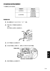
1 POWER 开关在"OFF"位置。 2 3 4 中 文 C-8
1 POWER 开关在"OFF"位置。 2 3 4 中 文 C-8

AJHVF21G User Guide
Page 120
... (800) 334-4880 Emergency after hour parts orders (800) 334-4881 TECHNICAL SUPPORT: Emergency 24 Hour Service (800) 222-0741 Panasonic Canada Inc. 5770 Ambler Drive, Mississauga, Ontario L4W 2T3 (905) 624-5010 Panasonic de Mexico S.A. Av angel Urraza Num. 1209 Col. PANASONIC BROADCAST & TELEVISION SYSTEMS COMPANY UNIT COMPANY OF PANASONIC CORPORATION OF NORTH AMERICA Executive Office: One...
... (800) 334-4880 Emergency after hour parts orders (800) 334-4881 TECHNICAL SUPPORT: Emergency 24 Hour Service (800) 222-0741 Panasonic Canada Inc. 5770 Ambler Drive, Mississauga, Ontario L4W 2T3 (905) 624-5010 Panasonic de Mexico S.A. Av angel Urraza Num. 1209 Col. PANASONIC BROADCAST & TELEVISION SYSTEMS COMPANY UNIT COMPANY OF PANASONIC CORPORATION OF NORTH AMERICA Executive Office: One...


