Dvcpro Hd Camera
Page 5
... recording/playback function section 14 2-4 Menu operation section 17 2-5 Time code related section 18 2-6 Warning/status display section 19 2-7 Display window and its displays 19 2-8 Viewfinder section 21 Chapter 3 Recording and playback ....... 22 3-1 Cassette tapes 22 3-2 Basic procedures 23 3-3 Scene-to-scene continuity 25 3-4 To record video signals of a few seconds...
... recording/playback function section 14 2-4 Menu operation section 17 2-5 Time code related section 18 2-6 Warning/status display section 19 2-7 Display window and its displays 19 2-8 Viewfinder section 21 Chapter 3 Recording and playback ....... 22 3-1 Cassette tapes 22 3-2 Basic procedures 23 3-3 Scene-to-scene continuity 25 3-4 To record video signals of a few seconds...

Dvcpro Hd Camera
Page 6
... 5-8 Attaching the rain cover 88 5-9 Attacching the FRONT AUDIO LEVEL control knob 88 5-10 Connection of the remote control unit (AJ-RC10G 89 5-11 Connection of the external switch 89 Chapter 6 Maintenance and inspections 90 6-1 Inspections prior to shooting 90 6-1-1 6-1-2...90 Inspecting the VTR unit 91 Self-diagnosis function 92 6-2 Maintenance 93 6-2-1 Condensation 93 6-2-2 Head cleaning 93 6-2-3 Cleaning inside the viewfinder 93 6-2-4 Phenomena inherent to CCD cameras 93 6-2-5 Replacing the backup battery 93 6-2-6 Connectors and signals 94 6-3 Warning system 98 6-3-1...
... 5-8 Attaching the rain cover 88 5-9 Attacching the FRONT AUDIO LEVEL control knob 88 5-10 Connection of the remote control unit (AJ-RC10G 89 5-11 Connection of the external switch 89 Chapter 6 Maintenance and inspections 90 6-1 Inspections prior to shooting 90 6-1-1 6-1-2...90 Inspecting the VTR unit 91 Self-diagnosis function 92 6-2 Maintenance 93 6-2-1 Condensation 93 6-2-2 Head cleaning 93 6-2-3 Cleaning inside the viewfinder 93 6-2-4 Phenomena inherent to CCD cameras 93 6-2-5 Replacing the backup battery 93 6-2-6 Connectors and signals 94 6-3 Warning system 98 6-3-1...

Dvcpro Hd Camera
Page 8
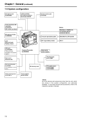
...provided HD SDI outputs are output, valid frame information is possible to page 31) O Remote control connector By connecting the remote control unit (AJ-RC10G), which is available as an optional accessory. (Refer to page 86) 1-3 Features of return video signals It is possible to shoot... the DVCPRO output connector, it is possible to improve mobility. Since it possible to record in intervals with a minimum recording time in the viewfinder to confirm programs. (Only video signals from four channels to page 89) 8 This is particularly useful for one frame. With memory control,...
...provided HD SDI outputs are output, valid frame information is possible to page 31) O Remote control connector By connecting the remote control unit (AJ-RC10G), which is available as an optional accessory. (Refer to page 86) 1-3 Features of return video signals It is possible to shoot... the DVCPRO output connector, it is possible to improve mobility. Since it possible to record in intervals with a minimum recording time in the viewfinder to confirm programs. (Only video signals from four channels to page 89) 8 This is particularly useful for one frame. With memory control,...

Dvcpro Hd Camera
Page 9
This means that are used frequently. (Refer to page 88) O Viewfinder connection From the viewfinder connector of the unit, 1080-59.94i or 1080-50i signals are output. Furthermore, signals are ...129 (5-1/8) 62 (2-1/2) 329 (13) 102 (4-1/16) 204 (8-1/16) 271 (10-11/16) 9 Confirm images in multi formats by connecting the viewfinder (AJ-HVF21G), which is available as an optional accessory. (Refer to page 50) O User button On the side panel of the unit, three user buttons... the position where the unit is optimally balanced for switching the frequencies of the connected viewfinder.
This means that are used frequently. (Refer to page 88) O Viewfinder connection From the viewfinder connector of the unit, 1080-59.94i or 1080-50i signals are output. Furthermore, signals are ...129 (5-1/8) 62 (2-1/2) 329 (13) 102 (4-1/16) 204 (8-1/16) 271 (10-11/16) 9 Confirm images in multi formats by connecting the viewfinder (AJ-HVF21G), which is available as an optional accessory. (Refer to page 50) O User button On the side panel of the unit, three user buttons... the position where the unit is optimally balanced for switching the frequencies of the connected viewfinder.
Dvcpro Hd Camera
Page 10
... UniSlot wireless microphone receiver: Sennheiser EK3041 Remote control unit: AJ-RC10G 2-inch electronic HD viewfinder: AJ-HVF21G (Mic holder provided) Microphone holder: AJ-MH800G Lens (Bayonet type): Fujinon, Canon GPS unit: AJ-GPS900G (This unit is not available in European region.) Rain cover: SHAN-RC700 Camera-Recorder: AJ-HDX900 Battery PROPAC14, TRIMPAC14, HYTRON50/100/120, DIONIC90/100...
... UniSlot wireless microphone receiver: Sennheiser EK3041 Remote control unit: AJ-RC10G 2-inch electronic HD viewfinder: AJ-HVF21G (Mic holder provided) Microphone holder: AJ-MH800G Lens (Bayonet type): Fujinon, Canon GPS unit: AJ-GPS900G (This unit is not available in European region.) Rain cover: SHAN-RC700 Camera-Recorder: AJ-HDX900 Battery PROPAC14, TRIMPAC14, HYTRON50/100/120, DIONIC90/100...

Dvcpro Hd Camera
Page 11
Push this button in place while the lens is not attached. ; Insert the connector for the viewfinder firmly until it has been attached to the lens mount. : Lens mount cap To remove the cap, push the lens lever 9 up. For further details ... circuit breaker is tripped and the power is connected here. GPS connector GPS unit AJ-GPS900G (optional accessory) is connected here. (GPS unit AJ-GPS900G is connected to this mount. 9 Lens lever This lever is carried on . 5 VF connector Viewfinder AJ-HVF21G (optional accessory) is automatically turned off to protect the unit. Chapter 2 Parts...
Push this button in place while the lens is not attached. ; Insert the connector for the viewfinder firmly until it has been attached to the lens mount. : Lens mount cap To remove the cap, push the lens lever 9 up. For further details ... circuit breaker is tripped and the power is connected here. GPS connector GPS unit AJ-GPS900G (optional accessory) is connected here. (GPS unit AJ-GPS900G is connected to this mount. 9 Lens lever This lever is carried on . 5 VF connector Viewfinder AJ-HVF21G (optional accessory) is automatically turned off to protect the unit. Chapter 2 Parts...

Dvcpro Hd Camera
Page 13
... of the warning alarms from the earphones which is used to adjust the volume of audio channels 3 and 4 are output in the display window and viewfinder change when this switch is possible to control REC start/stop by connecting an external switch to this connector. CH1/3 ST CH2/4 MONITOR SELECT CH1...
... of the warning alarms from the earphones which is used to adjust the volume of audio channels 3 and 4 are output in the display window and viewfinder change when this switch is possible to control REC start/stop by connecting an external switch to this connector. CH1/3 ST CH2/4 MONITOR SELECT CH1...
Dvcpro Hd Camera
Page 14
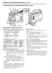
... FILTER knob (inside, small diameter) 1: CLEAR (transparent) 2: 1/4 ND 3: 1/16 ND 4: 1/64 ND ∫ Examples of filter selection Shooting conditions CC filter Sunrise, sunset, inside the viewfinder is decreased. 5 GAIN selector switch This is used when the electronic shutter speed is held down at the time of the video amplifier in accordance...
... FILTER knob (inside, small diameter) 1: CLEAR (transparent) 2: 1/4 ND 3: 1/16 ND 4: 1/64 ND ∫ Examples of filter selection Shooting conditions CC filter Sunrise, sunset, inside the viewfinder is decreased. 5 GAIN selector switch This is used when the electronic shutter speed is held down at the time of the video amplifier in accordance...
Dvcpro Hd Camera
Page 15
... monitor. The factory setting for instance, there is 3200K, but this position, the SAVE lamp inside the viewfinder lights. SAVE : This is released. When the switch is pressed, recording on the viewfinder screen. is set the VTR SAVE/STBY switch to SAVE, and then again to "4-9-4 Setting the color ... at times when, for the white balance is no marker display) 5 A, and so on the viewfinder to the SAVE mode. Each time it is switched ON, the display on the viewfinder screen immediately before the power was switched OFF will be changed to this position at the STBY position...
... monitor. The factory setting for instance, there is 3200K, but this position, the SAVE lamp inside the viewfinder lights. SAVE : This is released. When the switch is pressed, recording on the viewfinder screen. is set the VTR SAVE/STBY switch to SAVE, and then again to "4-9-4 Setting the color ... at times when, for the white balance is no marker display) 5 A, and so on the viewfinder to the SAVE mode. Each time it is switched ON, the display on the viewfinder screen immediately before the power was switched OFF will be changed to this position at the STBY position...

Dvcpro Hd Camera
Page 16
...For details on the video output, refer to "4-8-1 Settings of signals output from the MON OUT connector." A REMOTE (remote control) connector The AJ-RC10G remote control unit (optional accessory) is pressed to insert or eject the cassette. F PLAY/PAUSE button This is pressed to view the ... the superimposing of the characters onto the images which are to be superimposed onto the images output from the VIDEO OUT connector. in the viewfinder screen by entering HD-Y signals. OFF : The characters are superimposed onto the images. Composite video signals may be input as well. D...
...For details on the video output, refer to "4-8-1 Settings of signals output from the MON OUT connector." A REMOTE (remote control) connector The AJ-RC10G remote control unit (optional accessory) is pressed to insert or eject the cassette. F PLAY/PAUSE button This is pressed to view the ... the superimposing of the characters onto the images which are to be superimposed onto the images output from the VIDEO OUT connector. in the viewfinder screen by entering HD-Y signals. OFF : The characters are superimposed onto the images. Composite video signals may be input as well. D...

Dvcpro Hd Camera
Page 19
... within the VTR unit, this lamp flashes or lights. 4 LIGHT switch This controls the lighting of condensation on the head drum SLACK: Problem in the viewfinder. 2 Back tally switch This is set all 7 segments up For details, refer to "6-3 Warning system." 19 Each time it is set to CH3/4, numbers 3 and...
... within the VTR unit, this lamp flashes or lights. 4 LIGHT switch This controls the lighting of condensation on the head drum SLACK: Problem in the viewfinder. 2 Back tally switch This is set all 7 segments up For details, refer to "6-3 Warning system." 19 Each time it is set to CH3/4, numbers 3 and...
Dvcpro Hd Camera
Page 21
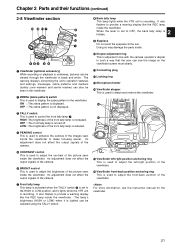
...concerning the unit's operation statuses and settings, messages, zebra patterns and markers (safety zone markers and center marker) can also be seen in the viewfinder. 2 ZEBRA (zebra pattern) switch This is used to display the zebra pattern in black and white. Its adjustment does not affect the output ...does not affect the output signals of the camera. 6 BRIGHT control This is used to adjust the brightness of the picture seen inside the viewfinder. It also flashes to enhance the outlines of the front tally lamp is reduced. 4 PEAKING control This is used to control the front ...
...concerning the unit's operation statuses and settings, messages, zebra patterns and markers (safety zone markers and center marker) can also be seen in the viewfinder. 2 ZEBRA (zebra pattern) switch This is used to display the zebra pattern in black and white. Its adjustment does not affect the output ...does not affect the output signals of the camera. 6 BRIGHT control This is used to adjust the brightness of the picture seen inside the viewfinder. It also flashes to enhance the outlines of the front tally lamp is reduced. 4 PEAKING control This is used to control the front ...

Dvcpro Hd Camera
Page 23
... figure below, and then proceed to 0 dB; Up to loading the cassette 1 Attach a fully charged battery pack. Next, set each switch as shown in the viewfinder, the type of set to operate. GAIN: Normally set battery is shown on how to perform these inspections, refer to "6-1 Inspections prior to a more segments...
... figure below, and then proceed to 0 dB; Up to loading the cassette 1 Attach a fully charged battery pack. Next, set each switch as shown in the viewfinder, the type of set to operate. GAIN: Normally set battery is shown on how to perform these inspections, refer to "6-1 Inspections prior to a more segments...
Dvcpro Hd Camera
Page 24
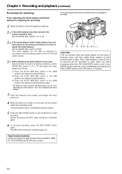
... the VTR SAVE/STBY switch is no time to adjust the white balance: Set the WHITE BAL switch to PRST. The REC lamp inside the viewfinder lights. 3 1 4 5, 6 2-3 2-1, 2, 3 CAUTION: The unit records video and audio signals into the built-in the memory and there is set the WHITE ... BAL switch to the AWB position and adjust the white balance again. * For details on tape. During recording, the REC lamp inside the viewfinder goes off. Chapter 3 Recording and playback (continued) Procedure for shooting From adjusting the white balance and black balance to stopping the recording From ...
... the VTR SAVE/STBY switch is no time to adjust the white balance: Set the WHITE BAL switch to PRST. The REC lamp inside the viewfinder lights. 3 1 4 5, 6 2-3 2-1, 2, 3 CAUTION: The unit records video and audio signals into the built-in the memory and there is set the WHITE ... BAL switch to the AWB position and adjust the white balance again. * For details on tape. During recording, the REC lamp inside the viewfinder goes off. Chapter 3 Recording and playback (continued) Procedure for shooting From adjusting the white balance and black balance to stopping the recording From ...

Dvcpro Hd Camera
Page 25
... to the next at an accuracy of the lens or the USER button that is allocated the RET SW function is pressed once in the viewfinder screen flashes. If the unit is in the "SAVE" position, the jump operation is disabled. If the RET button of +1 frame or less can be...
... to the next at an accuracy of the lens or the USER button that is allocated the RET SW function is pressed once in the viewfinder screen flashes. If the unit is in the "SAVE" position, the jump operation is disabled. If the RET button of +1 frame or less can be...

Dvcpro Hd Camera
Page 26
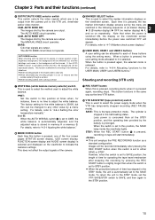
... supplied during a playback or rec-review operation. ≥ When recording has been started by pressing the REC START button or the VTR button on the viewfinder screen. OFF: Recording starts about 0.4 seconds after the power is turned on the lens. ≥ The video data and audio data are not stored in...
... supplied during a playback or rec-review operation. ≥ When recording has been started by pressing the REC START button or the VTR button on the viewfinder screen. OFF: Recording starts about 0.4 seconds after the power is turned on the lens. ≥ The video data and audio data are not stored in...

Dvcpro Hd Camera
Page 27
... the moment when the button is turned off . 2) Perform a menu operation and select OFF as the ones in the display window also appear inside the viewfinder, and the TALLY lamp lights while recording is underway. In order to use the menu operations to 2 minutes or more , the tally lamp blinks at...
... the moment when the button is turned off . 2) Perform a menu operation and select OFF as the ones in the display window also appear inside the viewfinder, and the TALLY lamp lights while recording is underway. In order to use the menu operations to 2 minutes or more , the tally lamp blinks at...

Dvcpro Hd Camera
Page 28
... always in the memory are being recorded, the LED of either USER MAIN or USER1/USER2 buttons in the display window also appear inside the viewfinder, and the TALLY lamp lights while recording is underway. Checkpoints common to all the tape function buttons (EJECT, REW, FF and PLAY/STILL) except STOP...
... always in the memory are being recorded, the LED of either USER MAIN or USER1/USER2 buttons in the display window also appear inside the viewfinder, and the TALLY lamp lights while recording is underway. Checkpoints common to all the tape function buttons (EJECT, REW, FF and PLAY/STILL) except STOP...

Dvcpro Hd Camera
Page 29
.... Even if the TCG switch is at the VTR position during the rec-review operation, the rec-review images are output not only to the viewfinder but to the SET position or the FRUN position, the time code will end up being recorded by a backup VTR that has been connected, these...; After executing the rec-view operation, the time code at different speeds Black-and-white playback images can be regenerated to the settings in the viewfinder by establishing the cue mode (PLAY + FF), review mode (PLAY + REW), high-speed fast forward playback mode (FF) or high-speed rewind playback mode (REW...
.... Even if the TCG switch is at the VTR position during the rec-review operation, the rec-review images are output not only to the viewfinder but to the SET position or the FRUN position, the time code will end up being recorded by a backup VTR that has been connected, these...; After executing the rec-view operation, the time code at different speeds Black-and-white playback images can be regenerated to the settings in the viewfinder by establishing the cue mode (PLAY + FF), review mode (PLAY + REW), high-speed fast forward playback mode (FF) or high-speed rewind playback mode (REW...

Dvcpro Hd Camera
Page 30
... "OFF" and then turned "ON" again. Chapter 4 Adjustments and settings for SYSTEM MODE item are changed, the message "TURN POWER: OFF" is displayed in the viewfinder screen. When settings for recording 4-1 Multi Format 4-1-1 Video system and Recording format The unit employs a progressive scan (full pixel reading) CCD system.
... "OFF" and then turned "ON" again. Chapter 4 Adjustments and settings for SYSTEM MODE item are changed, the message "TURN POWER: OFF" is displayed in the viewfinder screen. When settings for recording 4-1 Multi Format 4-1-1 Video system and Recording format The unit employs a progressive scan (full pixel reading) CCD system.
