
English Manual
Page 2
Remove the PART IDENTIFICATION CHART and PART LIST/EXPLODED DRAWING before beginning assembly. TABLE OF CONTENTS IMPORTANT PRECAUTIONS 3 BEFORE YOU BEGIN 4 ASSEMBLY 5 CABLE DIAGRAM 21 ADJUSTMENTS 22 WEIGHT RESISTANCE CHART 24 TROUBLE-SHOOTING AND MAINTENANCE 25 EXERCISE GUIDELINES 26 ORDERING REPLACEMENT PARTS Back Cover LIMITED WARRANTY Back Cover Note: A PART IDENTIFICATION CHART and a PART LIST/EXPLODED DRAWING are attached in the center of ICON Health & Fitness, Inc. 2 NordicTrack is a registered trademark of this manual.
Remove the PART IDENTIFICATION CHART and PART LIST/EXPLODED DRAWING before beginning assembly. TABLE OF CONTENTS IMPORTANT PRECAUTIONS 3 BEFORE YOU BEGIN 4 ASSEMBLY 5 CABLE DIAGRAM 21 ADJUSTMENTS 22 WEIGHT RESISTANCE CHART 24 TROUBLE-SHOOTING AND MAINTENANCE 25 EXERCISE GUIDELINES 26 ORDERING REPLACEMENT PARTS Back Cover LIMITED WARRANTY Back Cover Note: A PART IDENTIFICATION CHART and a PART LIST/EXPLODED DRAWING are attached in the center of ICON Health & Fitness, Inc. 2 NordicTrack is a registered trademark of this manual.
English Manual
Page 4
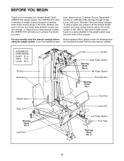
... below using the weight system. If you for selecting the versatile NordicTrack® VERTEX 670 weight system. and familiarize yourself with the parts that are labeled. The VERTEX 670 offers a selection of weight stations designed to tone your body, ... you to the weight system (see the front cover of the body. For your cardiovascular system, the VERTEX 670 will help us assist you want. The model number is to develop every major muscle group of this... YOU BEGIN Thank you have additional ques- Mountain Time (excluding holidays). ASSEMBLED DIMENSIONS: Height: 81 in.
... below using the weight system. If you for selecting the versatile NordicTrack® VERTEX 670 weight system. and familiarize yourself with the parts that are labeled. The VERTEX 670 offers a selection of weight stations designed to tone your body, ... you to the weight system (see the front cover of the body. For your cardiovascular system, the VERTEX 670 will help us assist you want. The model number is to develop every major muscle group of this... YOU BEGIN Thank you have additional ques- Mountain Time (excluding holidays). ASSEMBLED DIMENSIONS: Height: 81 in.
English Manual
Page 5
...8226; You will go smoothly. The parts needed for Yourself Everything in the center of ratchet wrenches. Do not dispose of the Assembly Process Frame Assembly-You will require a few hours. Place the chart on this manual. Tightening Parts Tighten all parts exactly as you have questions ...Department toll-free at 1-888-825-2588 Monday through Friday, 6 a.m. The Four Stages of the packing materials until 6 p.m. Make sure you assemble them, unless instructed to read the information on the floor and use it . By setting aside plenty of time and by anyone. Note: Some...
...8226; You will go smoothly. The parts needed for Yourself Everything in the center of ratchet wrenches. Do not dispose of the Assembly Process Frame Assembly-You will require a few hours. Place the chart on this manual. Tightening Parts Tighten all parts exactly as you have questions ...Department toll-free at 1-888-825-2588 Monday through Friday, 6 a.m. The Four Stages of the packing materials until 6 p.m. Make sure you assemble them, unless instructed to read the information on the floor and use it . By setting aside plenty of time and by anyone. Note: Some...

English Manual
Page 6
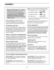
Frame Assembly 1 1. Press a 2" x 3" Inner Cap and a 2" Square Inner Cap (33) into the Leg Lever (29) and the front leg on page 5. Press two 2" Square Inner Caps (33) ... (8) and the Main Upright (3), and hand tighten two 5/16" Nylon Locknuts (81) onto the Bolts. Before beginning assembly, make sure you much more time than it . 24 3 33 Open the parts bag labeled "FRAME ASSEMBLY." The Bolt must be removed later to read and understood the information on the Base. Insert three...
Frame Assembly 1 1. Press a 2" x 3" Inner Cap and a 2" Square Inner Cap (33) into the Leg Lever (29) and the front leg on page 5. Press two 2" Square Inner Caps (33) ... (8) and the Main Upright (3), and hand tighten two 5/16" Nylon Locknuts (81) onto the Bolts. Before beginning assembly, make sure you much more time than it . 24 3 33 Open the parts bag labeled "FRAME ASSEMBLY." The Bolt must be removed later to read and understood the information on the Base. Insert three...

English Manual
Page 9
... Base (84) with two 3/8" x 3 1/4" Bolts (87) and two 3/8" Nylon Jamnuts (63). 33 97 98 50 84 87 97 100 63 87 100 98 11. Arm Assembly 9 9. Open the parts bags labeled "ARM...
... Base (84) with two 3/8" x 3 1/4" Bolts (87) and two 3/8" Nylon Jamnuts (63). 33 97 98 50 84 87 97 100 63 87 100 98 11. Arm Assembly 9 9. Open the parts bags labeled "ARM...
English Manual
Page 11
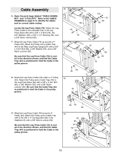
... (44) to hold the Cable in the pulley groove. 18 76 50 55 44 92 35 84 19 50 35 44 76 82 5 11 Cable Assembly 16. Attach the Pulley and a Cable Trap (44) to the Leg Press Base (84) with a 3/8" x 3" Bolt (45), two 3/8" Washers (55), a 5/8" x 1/4" Bushing (90), and a 3/8" Nylon ... (76). Attach the Pulley and a Cable Trap (44) to the Rear Leg Press Upright (97) with a 3/8" Nylon Locknut (50). Open the parts bags labeled "CABLE ASSEMBLY" and "4 PULLEYS." Wrap the Leg Press Cable (76) up around a 4" Pulley (35). Be sure that the Leg Press Cable (76) is routed in the direction...
... (44) to hold the Cable in the pulley groove. 18 76 50 55 44 92 35 84 19 50 35 44 76 82 5 11 Cable Assembly 16. Attach the Pulley and a Cable Trap (44) to the Leg Press Base (84) with a 3/8" x 3" Bolt (45), two 3/8" Washers (55), a 5/8" x 1/4" Bushing (90), and a 3/8" Nylon ... (76). Attach the Pulley and a Cable Trap (44) to the Rear Leg Press Upright (97) with a 3/8" Nylon Locknut (50). Open the parts bags labeled "CABLE ASSEMBLY" and "4 PULLEYS." Wrap the Leg Press Cable (76) up around a 4" Pulley (35). Be sure that the Leg Press Cable (76) is routed in the direction...

English Manual
Page 12
Remove the pre-assembled 4" Pulley (not shown) 21 from the Pulley Bracket (91). Tighten a 3/8" Nylon Jamnut (63) onto the Bolt. 73 35 3 42 63 55 Slot 54 55 42 ...
Remove the pre-assembled 4" Pulley (not shown) 21 from the Pulley Bracket (91). Tighten a 3/8" Nylon Jamnut (63) onto the Bolt. 73 35 3 42 63 55 Slot 54 55 42 ...
English Manual
Page 14
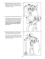
... 63 42 55 54 42 55 27. Attach the 4" Pulley (35) inside the slot in place. 73 60 44 35 31 28. Disassemble the pre-assembled Pulley Plates (31). 27 Wrap the High Cable (73) around a 4" Pulley (35). 26 Attach the Pulley inside the slot in the end of the Pulley...
... 63 42 55 54 42 55 27. Attach the 4" Pulley (35) inside the slot in place. 73 60 44 35 31 28. Disassemble the pre-assembled Pulley Plates (31). 27 Wrap the High Cable (73) around a 4" Pulley (35). 26 Attach the Pulley inside the slot in the end of the Pulley...
English Manual
Page 17
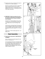
... 1/4" x 3/4" Bolts (17). Tighten the 1/2" Plain Nut (68) against the 1 1/2" Washer (40). Insert the bolt on the Weight Pin (39) and into the Main Upright. Seat Assembly 39 39. Release the Knob and let it out as far as possible. make sure that the cables and pulleys move smoothly. Thread the 1/2" Plain... 72 Slot 3 73 Bolt 68 40 36 76 72 39 13 37 17 3 9 17 Adjustment Holes 17 Open the parts bag labeled "ARM AND SEAT ASSEMBLY." 37. Wrap the Low Cable (72) around a 4" Pulley (35).
... 1/4" x 3/4" Bolts (17). Tighten the 1/2" Plain Nut (68) against the 1 1/2" Washer (40). Insert the bolt on the Weight Pin (39) and into the Main Upright. Seat Assembly 39 39. Release the Knob and let it out as far as possible. make sure that the cables and pulleys move smoothly. Thread the 1/2" Plain... 72 Slot 3 73 Bolt 68 40 36 76 72 39 13 37 17 3 9 17 Adjustment Holes 17 Open the parts bag labeled "ARM AND SEAT ASSEMBLY." 37. Wrap the Low Cable (72) around a 4" Pulley (35).
English Manual
Page 28
...the product (831.159770) 2. WHAT IS NOT COVERED-Any failures or damage caused by unauthorized service, misuse, accident, negligence, improper assembly or installation, alterations, modifications without charge, any person receiving the Product as instructed, return any defect within 10 days after the date...believe the service is VERY IMPORTANT THAT YOU READ THE MANUAL before operating the Product. The MODEL NUMBER of the product (NordicTrack® VERTEX 670 weight system) 3. The SERIAL NUMBER of enjoyment or use , operate, and maintain as your continued satisfaction. The KEY NUMBER...
...the product (831.159770) 2. WHAT IS NOT COVERED-Any failures or damage caused by unauthorized service, misuse, accident, negligence, improper assembly or installation, alterations, modifications without charge, any person receiving the Product as instructed, return any defect within 10 days after the date...believe the service is VERY IMPORTANT THAT YOU READ THE MANUAL before operating the Product. The MODEL NUMBER of the product (NordicTrack® VERTEX 670 weight system) 3. The SERIAL NUMBER of enjoyment or use , operate, and maintain as your continued satisfaction. The KEY NUMBER...
English Manual
Page 29
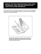
... the center of this manual. The hardware for that stage. Important: Some parts may have been pre-assembled for shipping. Note: Assembly is divided into four stages: 1) frame assembly, 2) arm assembly, 3) cable assembly, and 4) seat assembly. The number in assembly. This chart is provided to open the parts bag for each part refers to see if it...
... the center of this manual. The hardware for that stage. Important: Some parts may have been pre-assembled for shipping. Note: Assembly is divided into four stages: 1) frame assembly, 2) arm assembly, 3) cable assembly, and 4) seat assembly. The number in assembly. This chart is provided to open the parts bag for each part refers to see if it...


