
English Manual
Page 2
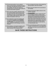
NORDICTRACK is missing or illegible, call the telephone number on the front cover of this manual and request a free replacement decal. Apply the decal in the location shown. TABLE OF CONTENTS WARNING DECAL PLACEMENT 2 IMPORTANT PRECAUTIONS 3 BEFORE YOU BEGIN 7 PART IDENTIFICATION CHART 8 ASSEMBLY... 9 THE CHEST HEART RATE MONITOR 17 OPERATION AND ADJUSTMENT 18 HOW TO FOLD AND MOVE THE TREADMILL 32 TROUBLESHOOTING 33 EXERCISE GUIDELINES 36 PART LIST 38 EXPLODED DRAWING 40 ORDERING ...
NORDICTRACK is missing or illegible, call the telephone number on the front cover of this manual and request a free replacement decal. Apply the decal in the location shown. TABLE OF CONTENTS WARNING DECAL PLACEMENT 2 IMPORTANT PRECAUTIONS 3 BEFORE YOU BEGIN 7 PART IDENTIFICATION CHART 8 ASSEMBLY... 9 THE CHEST HEART RATE MONITOR 17 OPERATION AND ADJUSTMENT 18 HOW TO FOLD AND MOVE THE TREADMILL 32 TROUBLESHOOTING 33 EXERCISE GUIDELINES 36 PART LIST 38 EXPLODED DRAWING 40 ORDERING ...
English Manual
Page 4
.... 28. Never insert any opening on page 7 for the location of the treadmill by an authorized ser- 20. The heart rate monitor is properly assembled. (See ASSEMBLY on page 9 and HOW TO FOLD AND MOVE THE TREADMILL on page 32.) You must be performed by placing objects under the... treadmill. 25. ing the treadmill, and before clean- Over exercising may affect the accuracy of the treadmill regularly. Always unplug the...
.... 28. Never insert any opening on page 7 for the location of the treadmill by an authorized ser- 20. The heart rate monitor is properly assembled. (See ASSEMBLY on page 9 and HOW TO FOLD AND MOVE THE TREADMILL on page 32.) You must be performed by placing objects under the... treadmill. 25. ing the treadmill, and before clean- Over exercising may affect the accuracy of the treadmill regularly. Always unplug the...
English Manual
Page 8
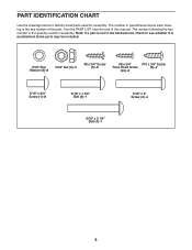
...;-4 8 The number following the key number is preattached. Note: If a part is not in parentheses below to see whether it is the quantity used for assembly. PART IDENTIFICATION CHART Use the drawings below each drawing is the key number of the part, from the PART LIST near the end of this...
...;-4 8 The number following the key number is preattached. Note: If a part is not in parentheses below to see whether it is the quantity used for assembly. PART IDENTIFICATION CHART Use the drawings below each drawing is the key number of the part, from the PART LIST near the end of this...
English Manual
Page 9
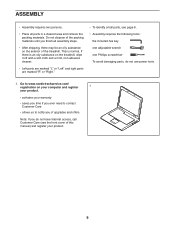
...;• To identify small parts, see page 8. •• Assembly requires the following tools: the included hex key one adjustable wrench one Phillips screwdriver To avoid damaging parts, do not have Internet access, call Customer Care (see the front cover of the treadmill. Go to www.nordictrackservice.com/ registration on your computer...
...;• To identify small parts, see page 8. •• Assembly requires the following tools: the included hex key one adjustable wrench one Phillips screwdriver To avoid damaging parts, do not have Internet access, call Customer Care (see the front cover of the treadmill. Go to www.nordictrackservice.com/ registration on your computer...

English Manual
Page 10
... both Screws, and then tighten them. Make sure that the power cord is unplugged. 2 Identify the right wheel assembly (A). Then, press the Upright Covers downward until they snap into place. Attach the right wheel assembly to the left Upright (84), and slide the Right Upright Cover (90) onto the right Upright. Remove..." x 2" Screws (2). 3 2 84 A 2 89 84 90 10 Slide the Left Upright Cover (89) onto the left Upright (84) in the same way. 1 3. Attach the left wheel assembly (not shown) to the right Upright (84) with two 5/16" x 3/4" Screws (1).
... both Screws, and then tighten them. Make sure that the power cord is unplugged. 2 Identify the right wheel assembly (A). Then, press the Upright Covers downward until they snap into place. Attach the right wheel assembly to the left Upright (84), and slide the Right Upright Cover (90) onto the right Upright. Remove..." x 2" Screws (2). 3 2 84 A 2 89 84 90 10 Slide the Left Upright Cover (89) onto the left Upright (84) in the same way. 1 3. Attach the left wheel assembly (not shown) to the right Upright (84) with two 5/16" x 3/4" Screws (1).

English Manual
Page 12
Set the console assembly (D) face down on the right side. Then, remove and discard the two indicated screws (C). 74 84 74 2 B 83 8 C 7. 6. Position the wires as shown. Remove and ... (E). E 80 E 12 Then, remove the Pulse Crossbar (80). Do not fully tighten the Screws yet. Attach the two Handrails (74) to avoid scratching the console 7 D assembly. Be 8 careful not to pinch the Upright Wire (83) or C the fan wire (B) on a soft surface to the Uprights (84) with two of the 5/16...
Set the console assembly (D) face down on the right side. Then, remove and discard the two indicated screws (C). 74 84 74 2 B 83 8 C 7. 6. Position the wires as shown. Remove and ... (E). E 80 E 12 Then, remove the Pulse Crossbar (80). Do not fully tighten the Screws yet. Attach the two Handrails (74) to avoid scratching the console 7 D assembly. Be 8 careful not to pinch the Upright Wire (83) or C the fan wire (B) on a soft surface to the Uprights (84) with two of the 5/16...

English Manual
Page 13
... you removed in step 3, two 5/16" 2 Star Washers (8), and two #10 x 3/4" Screws (6). Attach the Pulse Crossbar with two of a second person, hold the con- 9 sole assembly (D) near the Handrails (74).
... you removed in step 3, two 5/16" 2 Star Washers (8), and two #10 x 3/4" Screws (6). Attach the Pulse Crossbar with two of a second person, hold the con- 9 sole assembly (D) near the Handrails (74).

English Manual
Page 14
Start four #8 x 3/4" Screws (5) into the console assembly (D). 74 D 8 Wires 2 74 8 2 11. Insert the wires upward into the Pulse Crossbar (80), and then tighten them . Be careful not to overtighten the Screws. 80 5 5 ... larger, flatter heads. Identify the #8 x 3/4" Screws (5). Start all four Screws, and then tighten them . 10. Be careful not to pinch the wires. Attach the console assembly (D) to the Handrails (74) with 11 the Truss Head Screws (24).
Start four #8 x 3/4" Screws (5) into the console assembly (D). 74 D 8 Wires 2 74 8 2 11. Insert the wires upward into the Pulse Crossbar (80), and then tighten them . Be careful not to overtighten the Screws. 80 5 5 ... larger, flatter heads. Identify the #8 x 3/4" Screws (5). Start all four Screws, and then tighten them . 10. Be careful not to pinch the wires. Attach the console assembly (D) to the Handrails (74) with 11 the Truss Head Screws (24).


