

English Manual
Page 2
... DECAL PLACEMENT 2 IMPORTANT PRECAUTIONS 3 BEFORE YOU BEGIN 6 PART IDENTIFICATION CHART 7 ASSEMBLY 8 HOW TO USE THE ELLIPTICAL 14 FCC INFORMATION 25 MAINTENANCE AND TROUBLESHOOTING 26 EXERCISE GUIDELINES 29 PART LIST 31 ...EXPLODED DRAWING 33 ORDERING REPLACEMENT PARTS Back Cover LIMITED WARRANTY Back Cover WARNING DECAL PLACEMENT This drawing shows the location(s) of ICON Health & Fitness, Inc. 2 IFIT is a registered trademark of ICON Health & Fitness, Inc NORDICTRACK...
... DECAL PLACEMENT 2 IMPORTANT PRECAUTIONS 3 BEFORE YOU BEGIN 6 PART IDENTIFICATION CHART 7 ASSEMBLY 8 HOW TO USE THE ELLIPTICAL 14 FCC INFORMATION 25 MAINTENANCE AND TROUBLESHOOTING 26 EXERCISE GUIDELINES 29 PART LIST 31 ...EXPLODED DRAWING 33 ORDERING REPLACEMENT PARTS Back Cover LIMITED WARRANTY Back Cover WARNING DECAL PLACEMENT This drawing shows the location(s) of ICON Health & Fitness, Inc. 2 IFIT is a registered trademark of ICON Health & Fitness, Inc NORDICTRACK...

English Manual
Page 7
... the PART LIST near the end of this manual. Extra parts may be included. The number following the key number is the quantity needed for assembly. PART IDENTIFICATION CHART Use the drawings below each drawing is not in the hardware kit, check to identify the small parts needed for...
... the PART LIST near the end of this manual. Extra parts may be included. The number following the key number is the quantity needed for assembly. PART IDENTIFICATION CHART Use the drawings below each drawing is not in the hardware kit, check to identify the small parts needed for...
English Manual
Page 8
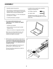
... not have Internet access, call Customer Care (see page 7. • In addition to the included tool(s), assembly requires the following tools: one Phillips screwdriver one rubber mallet Assembly may be easier if you have a set of wrenches. Have the second person hold the Frame to the ...Frame (1) with two M10 x 115mm Screws (104). ASSEMBLY • Assembly requires two persons. • Place all assembly steps. • Left parts are marked "L" or "Left" and right parts are marked "R" or "Right." • To ...
... not have Internet access, call Customer Care (see page 7. • In addition to the included tool(s), assembly requires the following tools: one Phillips screwdriver one rubber mallet Assembly may be easier if you have a set of wrenches. Have the second person hold the Frame to the ...Frame (1) with two M10 x 115mm Screws (104). ASSEMBLY • Assembly requires two persons. • Place all assembly steps. • Left parts are marked "L" or "Left" and right parts are marked "R" or "Right." • To ...
English Manual
Page 26
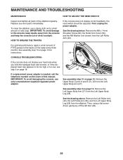
...IMPORTANT: To avoid damaging the console, use a damp cloth and a small amount of direct sunlight. Remove the Left Upper Body Arm (27) from the elliptical. Remove the Left Roller Arm (40), the Left Pedal Arm (38), and the Left Upper Body Leg (28) from the Left Upper Body Leg (...28). Then, using a flat screwdriver, gently pry off the left Disc (29). 26 See assembly step 9 on page 13 for instructions. See assembly step 13 on page 12. See the drawing below. HOW TO GREASE THE TRACKS For optimal performance, apply a small amount of PTFE...
...IMPORTANT: To avoid damaging the console, use a damp cloth and a small amount of direct sunlight. Remove the Left Upper Body Arm (27) from the elliptical. Remove the Left Roller Arm (40), the Left Pedal Arm (38), and the Left Upper Body Leg (28) from the Left Upper Body Leg (...28). Then, using a flat screwdriver, gently pry off the left Disc (29). 26 See assembly step 9 on page 13 for instructions. See assembly step 13 on page 12. See the drawing below. HOW TO GREASE THE TRACKS For optimal performance, apply a small amount of PTFE...
English Manual
Page 28
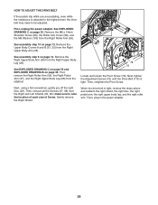
See EXPLODED DRAWING C on page 12. See assembly step 9 on page 35. Then, remove all the Screws (97, 98) from the Right Upper... the Right Pedal Arm (37), and the Right Upper Body Leg (26) from the Right Upper Body Leg (26). See assembly step 10 on page 34. Next, using a flat screwdriver, gently pry off the right Disc (29). Next, tighten the Adjustment...Then, retighten the Pivot Screw. First, unplug the power adapter. Remove the Right Upper Body Arm (25) from the elliptical. Remove the M8 x 14mm Shoulder Screw (89), the Roller Arm Cover (58), and the M8 Washer (103) from the Right...
See EXPLODED DRAWING C on page 12. See assembly step 9 on page 35. Then, remove all the Screws (97, 98) from the Right Upper... the Right Pedal Arm (37), and the Right Upper Body Leg (26) from the Right Upper Body Leg (26). See assembly step 10 on page 34. Next, using a flat screwdriver, gently pry off the right Disc (29). Next, tighten the Adjustment...Then, retighten the Pivot Screw. First, unplug the power adapter. Remove the Right Upper Body Arm (25) from the elliptical. Remove the M8 x 14mm Shoulder Screw (89), the Roller Arm Cover (58), and the M8 Washer (103) from the Right...
English Manual
Page 32
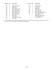
... change without notice. Power Adapter Lower Wire Upper Wire Pulse Wire Pulse Grip Back Pulse Grip Cap M4 x 12mm Flange Screw M2.6 x 33mm Bolt Set Assembly Tool General Grease Packet PTFE Grease Packet User's Manual Note: Specifications are not illustrated. 32 Description Key No. Description 101 2 102 2 103 8 104 4 105 2 106...
... change without notice. Power Adapter Lower Wire Upper Wire Pulse Wire Pulse Grip Back Pulse Grip Cap M4 x 12mm Flange Screw M2.6 x 33mm Bolt Set Assembly Tool General Grease Packet PTFE Grease Packet User's Manual Note: Specifications are not illustrated. 32 Description Key No. Description 101 2 102 2 103 8 104 4 105 2 106...


