
English Manual
Page 2
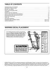
... TABLE OF CONTENTS WARNING DECAL PLACEMENT 2 IMPORTANT PRECAUTIONS 3 BEFORE YOU BEGIN 7 PART IDENTIFICATION CHART 8 ASSEMBLY 9 HOW TO USE THE TREADMILL 19 HOW TO FOLD AND MOVE THE TREADMILL 33 MAINTENANCE AND TROUBLESHOOTING 34 EXERCISE GUIDELINES 37 PART LIST 38 EXPLODED DRAWING 40 ORDERING REPLACEMENT PARTS Back...the telephone number on the front cover of the warning decals. The BLUETOOTH® word mark and logos are used under license. NORDICTRACK and IFIT are trademarks of ICON Health & Fitness, Inc. IOS is used under license. 2 and other countries and is a ...
... TABLE OF CONTENTS WARNING DECAL PLACEMENT 2 IMPORTANT PRECAUTIONS 3 BEFORE YOU BEGIN 7 PART IDENTIFICATION CHART 8 ASSEMBLY 9 HOW TO USE THE TREADMILL 19 HOW TO FOLD AND MOVE THE TREADMILL 33 MAINTENANCE AND TROUBLESHOOTING 34 EXERCISE GUIDELINES 37 PART LIST 38 EXPLODED DRAWING 40 ORDERING REPLACEMENT PARTS Back...the telephone number on the front cover of the warning decals. The BLUETOOTH® word mark and logos are used under license. NORDICTRACK and IFIT are trademarks of ICON Health & Fitness, Inc. IOS is used under license. 2 and other countries and is a ...
English Manual
Page 4
... is running. Adjust the speed in small increments to move the treadmill until it is walking on the treadmill, the noise level of high speeds. Never leave the treadmill unattended while it is capable of the treadmill will increase. DANGER: 30. The treadmill is properly assembled. (See ASSEMBLY on page 9 and HOW TO FOLD AND MOVE THE...
... is running. Adjust the speed in small increments to move the treadmill until it is walking on the treadmill, the noise level of high speeds. Never leave the treadmill unattended while it is capable of the treadmill will increase. DANGER: 30. The treadmill is properly assembled. (See ASSEMBLY on page 9 and HOW TO FOLD AND MOVE THE...
English Manual
Page 8
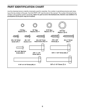
... (50)-2 #8 x 5/8" Machine Screw (26)-4 3/8" x 1 1/4" Screw (63)-2 3/8" x 1 3/4" Screw (62)-2 5/16" x 2 1/2" Screw (28)-4 3/8" x 2 1/4" Screw (7)-4 8 The number in the hardware kit, check to identify small parts used for assembly. The number following the key number is the quantity used for...
... (50)-2 #8 x 5/8" Machine Screw (26)-4 3/8" x 1 1/4" Screw (63)-2 3/8" x 1 3/4" Screw (62)-2 5/16" x 2 1/2" Screw (28)-4 3/8" x 2 1/4" Screw (7)-4 8 The number in the hardware kit, check to identify small parts used for assembly. The number following the key number is the quantity used for...
English Manual
Page 9
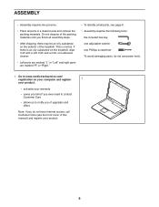
... and offers Note: If you finish all parts in a cleared area and remove the packing materials. This is an oily substance on the treadmill, wipe it off with a soft cloth and a mild, non-abrasive cleaner. • Left parts are marked "L" or "Left" and right parts...need to contact Customer Care • allows us to www.nordictrackservice.com/ registration on the exterior of the treadmill. If there is normal. ASSEMBLY • Assembly requires two persons. • Place all assembly steps. • After shipping, there may be an oily substance on your computer and register 1 your ...
... and offers Note: If you finish all parts in a cleared area and remove the packing materials. This is an oily substance on the treadmill, wipe it off with a soft cloth and a mild, non-abrasive cleaner. • Left parts are marked "L" or "Left" and right parts...need to contact Customer Care • allows us to www.nordictrackservice.com/ registration on the exterior of the treadmill. If there is normal. ASSEMBLY • Assembly requires two persons. • Place all assembly steps. • After shipping, there may be an oily substance on your computer and register 1 your ...
English Manual
Page 13
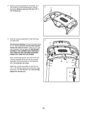
..., THE CONSOLE MAY BECOME DAMAGED WHEN YOU TURN ON THE POWER. do not, turn one connector and try again. Hold the console assembly (F) near the Pulse Crossbar (93). Connect the pulse wires (G, H). If they do not pinch any wires. Attach the console... assembly (F) with the four 1/4" x 1/2" Screws (4) that you set the console assembly onto the brackets on a soft surface to avoid scratching the console assembly. 8. See the inset drawing. do not fully tighten the Screws yet. 9 F 86 27 4 ...
..., THE CONSOLE MAY BECOME DAMAGED WHEN YOU TURN ON THE POWER. do not, turn one connector and try again. Hold the console assembly (F) near the Pulse Crossbar (93). Connect the pulse wires (G, H). If they do not pinch any wires. Attach the console... assembly (F) with the four 1/4" x 1/2" Screws (4) that you set the console assembly onto the brackets on a soft surface to avoid scratching the console assembly. 8. See the inset drawing. do not fully tighten the Screws yet. 9 F 86 27 4 ...
English Manual
Page 14
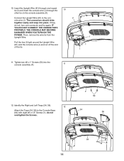
...Pull the ties (I 11. 10. Then, remove the wire tie from the Upright Wire. The connectors should slide together easily and snap into the console assembly (F). 11 12. Tighten two #8 x 1" Screws (50) into place. Insert the Upright Wire (81) through the 10 other tie on the console... assembly (F). Connect the Upright Wire (81) to the Console Base (64) with eight #8 x 1/2" Screws (1); IF YOU DO NOT CONNECT THE CONNECTORS PROPERLY, THE CONSOLE MAY ...
...Pull the ties (I 11. 10. Then, remove the wire tie from the Upright Wire. The connectors should slide together easily and snap into the console assembly (F). 11 12. Tighten two #8 x 1" Screws (50) into place. Insert the Upright Wire (81) through the 10 other tie on the console... assembly (F). Connect the Upright Wire (81) to the Console Base (64) with eight #8 x 1/2" Screws (1); IF YOU DO NOT CONNECT THE CONNECTORS PROPERLY, THE CONSOLE MAY ...
English Manual
Page 16
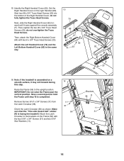
... 23 84 16. 15. Set the Right Handrail Cover on a smooth surface, it rests against the console assembly (F). do not overtighten the Truss Head Screws. Then, tighten the two #8 x 3/4" Truss Head Screws .... Attach the Latch Crossbar to the upright position. Note: If the treadmill is assembled on the right Handrail (86). Next, slide the Right Handrail Cover (92) forward until step 18 ...is facing the treadmill. do not fully tighten the Truss Head Screws. Raise the ...
... 23 84 16. 15. Set the Right Handrail Cover on a smooth surface, it rests against the console assembly (F). do not overtighten the Truss Head Screws. Then, tighten the two #8 x 3/4" Truss Head Screws .... Attach the Latch Crossbar to the upright position. Note: If the treadmill is assembled on the right Handrail (86). Next, slide the Right Handrail Cover (92) forward until step 18 ...is facing the treadmill. do not fully tighten the Truss Head Screws. Raise the ...
English Manual
Page 18
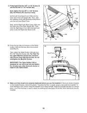
... #8 x 5/8" Machine Screws (26). To protect the floor or carpet, place a mat under the treadmill. Then, slide the Left Base Cover (82) downward and press it onto the Right Inner Base Cover. 19... 1/4" Screws (7) and the two 3/8" x 1 1/4" Screws (63). Press the two tabs (not shown) on the treadmill decals, remove the plastic. To avoid damage to adjust the walking belt (see pages 35 and 36). Keep the included ... (105) into the slots (N) in the console assembly (F). IMPORTANT: The Tablet Holder (105) is used to the console, keep the treadmill out of the Right Upright (90). 19.
... #8 x 5/8" Machine Screws (26). To protect the floor or carpet, place a mat under the treadmill. Then, slide the Left Base Cover (82) downward and press it onto the Right Inner Base Cover. 19... 1/4" Screws (7) and the two 3/8" x 1 1/4" Screws (63). Press the two tabs (not shown) on the treadmill decals, remove the plastic. To avoid damage to adjust the walking belt (see pages 35 and 36). Keep the included ... (105) into the slots (N) in the console assembly (F). IMPORTANT: The Tablet Holder (105) is used to the console, keep the treadmill out of the Right Upright (90). 19.


