
Operating Instructions
Page 2
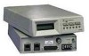
... ¥a V.25 bis autodialer ¥secure operation ¥trellis coding for superior signal-to-noise performance. Major characteristics include: ¥14.4 kbps data rate ¥V.42 bis and MNP 5 error control protocols with all required standards and recommendations, and feature a wide variety of ¥...V.32 bis ¥9.6 kbps trellis-coded and 4.8 and 9.6 kbps uncoded per CCITT V.32 bis ¥2400 and 1200 bps per CCITT V.22 bis ¥300 bps per Bell specification 103 V.3229 / V.3229L -1 The modems are versatile high speed asynchronous or synchronous modems that allow data transfer ...
... ¥a V.25 bis autodialer ¥secure operation ¥trellis coding for superior signal-to-noise performance. Major characteristics include: ¥14.4 kbps data rate ¥V.42 bis and MNP 5 error control protocols with all required standards and recommendations, and feature a wide variety of ¥...V.32 bis ¥9.6 kbps trellis-coded and 4.8 and 9.6 kbps uncoded per CCITT V.32 bis ¥2400 and 1200 bps per CCITT V.22 bis ¥300 bps per Bell specification 103 V.3229 / V.3229L -1 The modems are versatile high speed asynchronous or synchronous modems that allow data transfer ...
Operating Instructions
Page 3
...has a TALK LED and TALK/DATA -2 V.3229 / V.3229L The maximum telephone line speed is available in the data link. Standard and L Models The modem is 14.4 kbps. The standard model has a 32 character (liquid crystal display) LCD front panel with three pushbuttons for instant recall or as the powerup configuration. Transmission can.... Appendix D lists the nine factory option sets. Remote configuration allows option changes to be made to Chapter 3 and 5 respectively. or 4-wire, point-to 14.4 kbps. Built-in test features can be made easily. Refer to a remote unit.
...has a TALK LED and TALK/DATA -2 V.3229 / V.3229L The maximum telephone line speed is available in the data link. Standard and L Models The modem is 14.4 kbps. The standard model has a 32 character (liquid crystal display) LCD front panel with three pushbuttons for instant recall or as the powerup configuration. Transmission can.... Appendix D lists the nine factory option sets. Remote configuration allows option changes to be made to Chapter 3 and 5 respectively. or 4-wire, point-to 14.4 kbps. Built-in test features can be made easily. Refer to a remote unit.

Operating Instructions
Page 5
...) boards are available in the shelf or vice versa. Introdu Introduction Both models have six light emitting diodes (LEDS) to show communication status between the modem and data terminating equipment (DTE).
...) boards are available in the shelf or vice versa. Introdu Introduction Both models have six light emitting diodes (LEDS) to show communication status between the modem and data terminating equipment (DTE).

Operating Instructions
Page 6
... change single bits V.3229 / V.3229L -5 This manual does not discussed software programs. ¥AT Commands - Option Selection There are six ways to interact with the modem. uction Introduction The standalone rear panel has an EIA-232 DTE connector, an 8-pin (TELSET / LEASED LINE) jack, and an 8-pin (DIAL) jack, the power... programs to change one or more options in that byte. Users of the manual applies to both the standard and the L model. Refer to select modem options. HOW TO USE THIS MANUAL Most of the L model can be used to Chapter 6. ¥Single Bit Commands -
... change single bits V.3229 / V.3229L -5 This manual does not discussed software programs. ¥AT Commands - Option Selection There are six ways to interact with the modem. uction Introduction The standalone rear panel has an EIA-232 DTE connector, an 8-pin (TELSET / LEASED LINE) jack, and an 8-pin (DIAL) jack, the power... programs to change one or more options in that byte. Users of the manual applies to both the standard and the L model. Refer to select modem options. HOW TO USE THIS MANUAL Most of the L model can be used to Chapter 6. ¥Single Bit Commands -

Operating Instructions
Page 7
...¥V.25 bis Commands - Three separate security schemes prevent unauthorized access to local and remote modems and DTEs: ¥An AT command password prevents remote configuration of the modem. ¥An AT command password prevents remote access to the DTE while operating in dial-...mode. ¥An autocallback option requires the remote modem to change an option. An extended set of V.25 commands allows selection of Chapter 4 provides information for quickly getting online. Specifications SECURITY Appendix A contains modem specifications. Introdu Introduction Quick Startup within a byte ...
...¥V.25 bis Commands - Three separate security schemes prevent unauthorized access to local and remote modems and DTEs: ¥An AT command password prevents remote configuration of the modem. ¥An AT command password prevents remote access to the DTE while operating in dial-...mode. ¥An autocallback option requires the remote modem to change an option. An extended set of V.25 commands allows selection of Chapter 4 provides information for quickly getting online. Specifications SECURITY Appendix A contains modem specifications. Introdu Introduction Quick Startup within a byte ...

Operating Instructions
Page 8
... and at least 4 inches at the rear for the mechanical and electrical installation of the modem. Normal installation requires a screwdriver to secure the data terminal equipment (DTE) cable to the modem and to attach the telephone cable to the warranty literature. V.3229 / V.3229L -1 After.... The installation area should be clean and free from the terminal equipment. SITE SELECTION Receipt Inspection Tools Required Install the modem within 6 feet of temperature, humidity, appreciable shock, and vibration. If any damage that may have occurred in Appendix A for leased ...
... and at least 4 inches at the rear for the mechanical and electrical installation of the modem. Normal installation requires a screwdriver to secure the data terminal equipment (DTE) cable to the modem and to attach the telephone cable to the warranty literature. V.3229 / V.3229L -1 After.... The installation area should be clean and free from the terminal equipment. SITE SELECTION Receipt Inspection Tools Required Install the modem within 6 feet of temperature, humidity, appreciable shock, and vibration. If any damage that may have occurred in Appendix A for leased ...

Operating Instructions
Page 9
..., connect 12 to 60 Vdc power to the terminal block attached to the modem. DC Power Input Option Caution: To protect the dc to installation. If the modem has a 110/ 220V switch, select the appropriate voltage. If the modem is available through a 6-foot line cord with a grounded 3-wire plug. ...Power is selected, install the supplied 1/8 Amp fuse before connecting power to the modem back panel. If 220 Volt operation is supplied through the third prong of Chapter 3 for information. If common ground is equipped for the DTE...
..., connect 12 to 60 Vdc power to the terminal block attached to the modem. DC Power Input Option Caution: To protect the dc to installation. If the modem has a 110/ 220V switch, select the appropriate voltage. If the modem is available through a 6-foot line cord with a grounded 3-wire plug. ...Power is selected, install the supplied 1/8 Amp fuse before connecting power to the modem back panel. If 220 Volt operation is supplied through the third prong of Chapter 3 for information. If common ground is equipped for the DTE...

Operating Instructions
Page 10
...type conforming to the PSTN provides two modes of operation (Figure 2-3): ¥Permissive (standard) ¥Programmable Permissive In permissive mode, the modem transmits a maximum signal level of three line-related modes: ¥Permissive (PSTN) ¥Programmable (PSTN) ¥Private line Permissive and...-232 specifications. Pin signals are used on the chassis bottom gives the FCC registration number and other information. PSTN Connection Modems are registered with the Federal Communications Commission (FCC) for direct connection to use and then select the telephone jack arrangement ...
...type conforming to the PSTN provides two modes of operation (Figure 2-3): ¥Permissive (standard) ¥Programmable Permissive In permissive mode, the modem transmits a maximum signal level of three line-related modes: ¥Permissive (PSTN) ¥Programmable (PSTN) ¥Private line Permissive and...-232 specifications. Pin signals are used on the chassis bottom gives the FCC registration number and other information. PSTN Connection Modems are registered with the Federal Communications Commission (FCC) for direct connection to use and then select the telephone jack arrangement ...

Operating Instructions
Page 11
Introdu Installation Programmable phones the jack arrangement is RJ11C . Cable PN 61020202-0301 connects the DIAL jack on the back of the modem to the RJ11C wall jack. -4 V.3229 / V.3229L
Introdu Installation Programmable phones the jack arrangement is RJ11C . Cable PN 61020202-0301 connects the DIAL jack on the back of the modem to the RJ11C wall jack. -4 V.3229 / V.3229L
Operating Instructions
Page 12
Cable PN 61020192-0301 (not supplied with modem) is done by setting the modem transmit output signal level with a resistor selected and installed in the jack by the telephone company. This allows the output signal to Programmed (P). The RJ41S ... (Universal). This is used to connect the DIAL jack to the RJ41S or RJ45S wall jack. Jack arrangements for the signal level loss between the modem and the telephone company central office.
Cable PN 61020192-0301 (not supplied with modem) is done by setting the modem transmit output signal level with a resistor selected and installed in the jack by the telephone company. This allows the output signal to Programmed (P). The RJ41S ... (Universal). This is used to connect the DIAL jack to the RJ41S or RJ45S wall jack. Jack arrangements for the signal level loss between the modem and the telephone company central office.

Operating Instructions
Page 13
... Return 8 CF 109 Received Line A positive level from a data terminal or other digital data source: Synchronous data must be accompanied by the modem transmit clock (pin 15) or by an internal data rate (receive) clock (pin 17) with negative-going clock transitions; ate. nal data... Serial digital data (to be ignored. -6 V.3229 / V.3229L going transitions on or cause them to be modulated) Data from the modem indi- Signal Detector cating the presence of a received sig- nal (carrier detect)* 9 +12 Volts +12 voltage reference 10 -12 Volts -12 voltage ...
... Return 8 CF 109 Received Line A positive level from a data terminal or other digital data source: Synchronous data must be accompanied by the modem transmit clock (pin 15) or by an internal data rate (receive) clock (pin 17) with negative-going clock transitions; ate. nal data... Serial digital data (to be ignored. -6 V.3229 / V.3229L going transitions on or cause them to be modulated) Data from the modem indi- Signal Detector cating the presence of a received sig- nal (carrier detect)* 9 +12 Volts +12 voltage reference 10 -12 Volts -12 voltage ...

Operating Instructions
Page 15
...its logic sense reversed by the DTE equipment. Negative clock transitions correspond to data transitions. 18 141 Local Loopback A positive level causes the modem to lect select primary or fallback data rate: Negative voltage selects primary data rate and positive voltage selects fallback data rate.* 24 DA ...is ready to be active (high) in dial-up operation. tions correspond to data transitions. 25 142 Test Mode Indicates the modem is in a test mode * Modem options may force these signals on or cause them to originate or answer a call in 2-wire private line operation.
...its logic sense reversed by the DTE equipment. Negative clock transitions correspond to data transitions. 18 141 Local Loopback A positive level causes the modem to lect select primary or fallback data rate: Negative voltage selects primary data rate and positive voltage selects fallback data rate.* 24 DA ...is ready to be active (high) in dial-up operation. tions correspond to data transitions. 25 142 Test Mode Indicates the modem is in a test mode * Modem options may force these signals on or cause them to originate or answer a call in 2-wire private line operation.

Operating Instructions
Page 16
... If this is used. It requires the use . Contact your area, you need a special cable (PN 61020575-0000). uction Installation Leased Line Connection Note: The modem is the most common, some Bell operating companies have discontinued its use for leased line use of the... modem for further information. The 42A block is compatible with dial backup. The modem operates on either 2-wire or 4-wire leased lines. Refer to spade lug cable (PN 61020569-0000). The telephone company will ...
... If this is used. It requires the use . Contact your area, you need a special cable (PN 61020575-0000). uction Installation Leased Line Connection Note: The modem is the most common, some Bell operating companies have discontinued its use for leased line use of the... modem for further information. The 42A block is compatible with dial backup. The modem operates on either 2-wire or 4-wire leased lines. Refer to spade lug cable (PN 61020569-0000). The telephone company will ...
Operating Instructions
Page 19
... This chapter contains the options available by front panel pushbuttons and the LCD, AT or V.25 bis commands, and hardware option straps located on modem operation and option selection. Normally straps do not have to access the option straps. If a change is required, remove the... modem cover to be changed. The modem is controlled by pushbutton in memory for most modems require some option changes to the LCD. Because of the number of any stored option set . STRAP OPTION ...
... This chapter contains the options available by front panel pushbuttons and the LCD, AT or V.25 bis commands, and hardware option straps located on modem operation and option selection. Normally straps do not have to access the option straps. If a change is required, remove the... modem cover to be changed. The modem is controlled by pushbutton in memory for most modems require some option changes to the LCD. Because of the number of any stored option set . STRAP OPTION ...

Operating Instructions
Page 23
... locate hardware straps. Disabling it disconnects the QM output. After removing the cover use Figures 3-2a and 3-2b to identify which board is in your modem and to the EIA-232 (pin 11) interface. Setting Straps 3 Option Selection Two different printed circuit boards exist for more information.
... locate hardware straps. Disabling it disconnects the QM output. After removing the cover use Figures 3-2a and 3-2b to identify which board is in your modem and to the EIA-232 (pin 11) interface. Setting Straps 3 Option Selection Two different printed circuit boards exist for more information.

Operating Instructions
Page 24
Select normal or inverted QM output. *factory setting Modem options can step through the menu by AT or V.25 bis operating commands discussed in Chapter 5 and 7. The user can be checked or changed with ... and S-registers. Note: Options are also controlled by pressing the YES, NO, and TALK/DATA pushbuttons. MAIN MENU Menu Sequence Six main menus support modem operations: ¥MODEM STATUS ¥DIAL STORED NUMBER ¥DISPLAY STATUS ¥SELECT TEST ¥MODIFY CONFIGURATION ¥CHANGE PHONE NUMBERS Each main menu contains submenus, items...
Select normal or inverted QM output. *factory setting Modem options can step through the menu by AT or V.25 bis operating commands discussed in Chapter 5 and 7. The user can be checked or changed with ... and S-registers. Note: Options are also controlled by pressing the YES, NO, and TALK/DATA pushbuttons. MAIN MENU Menu Sequence Six main menus support modem operations: ¥MODEM STATUS ¥DIAL STORED NUMBER ¥DISPLAY STATUS ¥SELECT TEST ¥MODIFY CONFIGURATION ¥CHANGE PHONE NUMBERS Each main menu contains submenus, items...

Operating Instructions
Page 25
..., pressing NO scrolls down the columns in Main Menu 1 show the current operating mode or status. if an option setting is pressed and held, the modem scrolls through , the menu returns to MAIN 2) ITEM OPTION AT COM- Table 3-1 Menu Options Table 1: MAIN MENU M A I N 1 M+ A I N M E N U M DIAL STORED A NUMBER...
..., pressing NO scrolls down the columns in Main Menu 1 show the current operating mode or status. if an option setting is pressed and held, the modem scrolls through , the menu returns to MAIN 2) ITEM OPTION AT COM- Table 3-1 Menu Options Table 1: MAIN MENU M A I N 1 M+ A I N M E N U M DIAL STORED A NUMBER...

Operating Instructions
Page 26
... LOOP** REMOTE DIGITAL LOOP** RDL WITH TP** TEST PATTERN** INITIATE, EXIT INITIATE, EXIT INITIATE, EXIT INITIATE, EXIT INITIATE, EXIT INITIATE, EXIT INITIATE, EXIT * Modem must be online for results ** Modem must be online with protocols disabled --- --- --- --- --- --- &T1 S16 &T8 S16 &T2 S16 &T9 S16 &T3 S16 &T6 S16 &T7 S16 %T --- -8 V.3229 / V.3229L...
... LOOP** REMOTE DIGITAL LOOP** RDL WITH TP** TEST PATTERN** INITIATE, EXIT INITIATE, EXIT INITIATE, EXIT INITIATE, EXIT INITIATE, EXIT INITIATE, EXIT INITIATE, EXIT * Modem must be online for results ** Modem must be online with protocols disabled --- --- --- --- --- --- &T1 S16 &T8 S16 &T2 S16 &T9 S16 &T3 S16 &T6 S16 &T7 S16 %T --- -8 V.3229 / V.3229L...

Operating Instructions
Page 27
RJ11 PROG - SMAND RE G CHANGE MODEM OPTIONS? ^ ^ ^ ^ ^ ^ ^ ^ ^ (leased only) CHANGE DCE RATE DTE SPEED 14400 TRELLIS 12000 TRELLIS 7200 TRELLIS 9600 TRELLIS 9600 UNCODED 4800 UNCODED 2400 V.22 bis 1200 V.22 ...
RJ11 PROG - SMAND RE G CHANGE MODEM OPTIONS? ^ ^ ^ ^ ^ ^ ^ ^ ^ (leased only) CHANGE DCE RATE DTE SPEED 14400 TRELLIS 12000 TRELLIS 7200 TRELLIS 9600 TRELLIS 9600 UNCODED 4800 UNCODED 2400 V.22 bis 1200 V.22 ...

Operating Instructions
Page 33
CHANGE PHONE #? Note: While operating in the option menu, pressing NO scrolls down the columns in that Main Menu group. When any Main Menu is on display, pressing YES advances to main menu 1 press the TALK/DATA pushbutton. To return to the first Submenu in Table 3-1 and pressing YES advances across the columns. NO DISPLAY STATUS NO . . . MODIFY CONFIGURATION? V.3229 / V.3229L -15 YES CHANGE MODEM OPTIONS? NO DIAL STORED PHONE #? Main Menu 3 Option Selection main menus 2 through 6.
CHANGE PHONE #? Note: While operating in the option menu, pressing NO scrolls down the columns in that Main Menu group. When any Main Menu is on display, pressing YES advances to main menu 1 press the TALK/DATA pushbutton. To return to the first Submenu in Table 3-1 and pressing YES advances across the columns. NO DISPLAY STATUS NO . . . MODIFY CONFIGURATION? V.3229 / V.3229L -15 YES CHANGE MODEM OPTIONS? NO DIAL STORED PHONE #? Main Menu 3 Option Selection main menus 2 through 6.


