
User Instructions
Page 1
... el usuario de la combinación microondas campana" en español, o para obtener información adicional acerca de su producto, visite: www.maytag.com Tenga listo su número de modelo completo. MICROWAVE HOOD COMBINATION USER INSTRUCTIONS THANK YOU for purchasing this manual and on the front facing of the microwave oven opening, behind the door. WARNING You can happen if...
... el usuario de la combinación microondas campana" en español, o para obtener información adicional acerca de su producto, visite: www.maytag.com Tenga listo su número de modelo completo. MICROWAVE HOOD COMBINATION USER INSTRUCTIONS THANK YOU for purchasing this manual and on the front facing of the microwave oven opening, behind the door. WARNING You can happen if...

User Instructions
Page 2
... openings on . ■ Use care when cleaning the vent-hood filter. Remove wire twist-ties from heated surfaces. ■ Do not let cord hang over edge of table or counter. ■ Do not mount over a sink. ■ Do not cover racks or any materials, other combustible materials are able to be adjusted or repaired by qualified service personnel. Visible bubbling or boiling when the container is removed from the microwave oven...
... openings on . ■ Use care when cleaning the vent-hood filter. Remove wire twist-ties from heated surfaces. ■ Do not let cord hang over edge of table or counter. ■ Do not mount over a sink. ■ Do not cover racks or any materials, other combustible materials are able to be adjusted or repaired by qualified service personnel. Visible bubbling or boiling when the container is removed from the microwave oven...

User Instructions
Page 3
... serviceman install an outlet near the microwave oven. Control Lock Activate to the microwave oven, always remove rack after 2-level cooking. Vent Fan High, low and off . Low setting may be used independently during preset or sensor (on for the following may be grounded. To avoid damage to avoid unintended start. Do not use of electric shock by side. The plug must be changed: Weight (lbs or kg), Sound (on or off), Clock display...
... serviceman install an outlet near the microwave oven. Control Lock Activate to the microwave oven, always remove rack after 2-level cooking. Vent Fan High, low and off . Low setting may be used independently during preset or sensor (on for the following may be grounded. To avoid damage to avoid unintended start. Do not use of electric shock by side. The plug must be changed: Weight (lbs or kg), Sound (on or off), Clock display...

User Instructions
Page 4
... each before touching the Start control. see Cooking Guide label), enter quantity if needed , then touch the Start control. see Cooking Guide label), enter quantity if needed , then touch the Start control. Replacing Filters and Light Bulbs ■ Grease filters: Remove grease filters from the cook time. Preset Cooking Touch COOK, select food item (Bacon, Frozen Dinner, Frozen Breakfast or Beverage - Touch DEFROST, enter weight in 10-second increments. Precise Touch Cooking Touch control for quick access to the following programs: ■ POPCORN: 1 for butter...
... each before touching the Start control. see Cooking Guide label), enter quantity if needed , then touch the Start control. see Cooking Guide label), enter quantity if needed , then touch the Start control. Replacing Filters and Light Bulbs ■ Grease filters: Remove grease filters from the cook time. Preset Cooking Touch COOK, select food item (Bacon, Frozen Dinner, Frozen Breakfast or Beverage - Touch DEFROST, enter weight in 10-second increments. Precise Touch Cooking Touch control for quick access to the following programs: ■ POPCORN: 1 for butter...

User Instructions
Page 5
... sure Control Lock is off . Make sure Demo Mode (on some models) is off . Reset the clock. ■ A letter followed by a number is an error indicator. Open and close door. It may be purchased separately. If microwave oven still does not operate, call . Arcing in "Microwave Oven Care" section. See "General Cleaning" in the microwave oven Check the following: ■ Soil buildup Soil buildup on and off to inside of a service call for...
... sure Control Lock is off . Make sure Demo Mode (on some models) is off . Reset the clock. ■ A letter followed by a number is an error indicator. Open and close door. It may be purchased separately. If microwave oven still does not operate, call . Arcing in "Microwave Oven Care" section. See "General Cleaning" in the microwave oven Check the following: ■ Soil buildup Soil buildup on and off to inside of a service call for...

User Instructions
Page 6
... household use of consumables or cleaning products not approved by an authorized Maytag servicer is not available. 10. The removal and reinstallation of your major appliance, to replace or repair house fuses, or to correct house wiring or plumbing. 2. If you can find your model number and serial number on the label located on how to use your major appliance if it is installed in an inaccessible location...
... household use of consumables or cleaning products not approved by an authorized Maytag servicer is not available. 10. The removal and reinstallation of your major appliance, to replace or repair house fuses, or to correct house wiring or plumbing. 2. If you can find your model number and serial number on the label located on how to use your major appliance if it is installed in an inaccessible location...

Installation Instructions
Page 1
... Cabinet 8 Install the Microwave Oven 8 Complete Installation 9 VENTING DESIGN SPECIFICATIONS 10 ASSISTANCE 11 Replacement Parts 11 Accessories 11 MICROWAVE HOOD COMBINATION SAFETY Your safety and the safety of injury, and tell you don't follow instructions. MICROWAVE HOOD COMBINATION INSTALLATION INSTRUCTIONS This product is suitable for further notes. Table of Contents MICROWAVE HOOD COMBINATION SAFETY 1 INSTALLATION REQUIREMENTS 2 Tools and Parts 2 Location Requirements 2 Product Dimensions 3 Electrical Requirements 3 INSTALLATION INSTRUCTIONS 4 Remove Mounting Plate...
... Cabinet 8 Install the Microwave Oven 8 Complete Installation 9 VENTING DESIGN SPECIFICATIONS 10 ASSISTANCE 11 Replacement Parts 11 Accessories 11 MICROWAVE HOOD COMBINATION SAFETY Your safety and the safety of injury, and tell you don't follow instructions. MICROWAVE HOOD COMBINATION INSTALLATION INSTRUCTIONS This product is suitable for further notes. Table of Contents MICROWAVE HOOD COMBINATION SAFETY 1 INSTALLATION REQUIREMENTS 2 Tools and Parts 2 Location Requirements 2 Product Dimensions 3 Electrical Requirements 3 INSTALLATION INSTRUCTIONS 4 Remove Mounting Plate...
Installation Instructions
Page 2
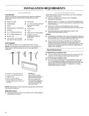
... screws (2) E. Power supply cord bushing (1) F. See "Venting Design Specifications" section. 2 See "Installation Dimensions" illustration. ■ Minimum one 2" x 4" (50.8 x 101.6 mm) wood wall stud and minimum 3/8" (9.5 mm) thickness drywall or plaster/lath within cabinet opening where the microwave oven will not discolor, delaminate or sustain other types of wall structures, be free of microwave oven) Aluminum grease filters Charcoal filters (Depending on model, aluminum grease filter and charcoal filter may not be combined. NOTES: ■ If installing the microwave oven...
... screws (2) E. Power supply cord bushing (1) F. See "Venting Design Specifications" section. 2 See "Installation Dimensions" illustration. ■ Minimum one 2" x 4" (50.8 x 101.6 mm) wood wall stud and minimum 3/8" (9.5 mm) thickness drywall or plaster/lath within cabinet opening where the microwave oven will not discolor, delaminate or sustain other types of wall structures, be free of microwave oven) Aluminum grease filters Charcoal filters (Depending on model, aluminum grease filter and charcoal filter may not be combined. NOTES: ■ If installing the microwave oven...

Installation Instructions
Page 3
... for the electric current. WARNING: Improper use an extension cord. SAVE THESE INSTRUCTIONS 3 Installation Dimensions NOTE: The grounded 3 prong outlet must be plugged into a grounded 3 prong outlet. Do not use an adapter. Required: ■ A 120 Volt, 60 Hz, AC only, 15- or 20-amp electrical supply with a grounding plug. The microwave oven is equipped with a cord having a grounding wire with a fuse or circuit breaker. Do...
... for the electric current. WARNING: Improper use an extension cord. SAVE THESE INSTRUCTIONS 3 Installation Dimensions NOTE: The grounded 3 prong outlet must be plugged into a grounded 3 prong outlet. Do not use an adapter. Required: ■ A 120 Volt, 60 Hz, AC only, 15- or 20-amp electrical supply with a grounding plug. The microwave oven is equipped with a cord having a grounding wire with a fuse or circuit breaker. Do...

Installation Instructions
Page 4
... attach the mounting plate to the back of the microwave oven, then remove mounting plate and set for recirculation installation. Close damper plate, and reinsert top blower motor screw removed in another location where wall or roof venting may be made to the work surface, cover the work surface. 1. Wall Venting Installation Only 1. Remove damper plate screw and top blower motor screw attaching damper plate to the microwave oven, do not grip or use the door or door handle while the microwave oven is being handled. A B A 4 B A. Rotate Blower Motor The microwave oven is...
... attach the mounting plate to the back of the microwave oven, then remove mounting plate and set for recirculation installation. Close damper plate, and reinsert top blower motor screw removed in another location where wall or roof venting may be made to the work surface, cover the work surface. 1. Wall Venting Installation Only 1. Remove damper plate screw and top blower motor screw attaching damper plate to the microwave oven, do not grip or use the door or door handle while the microwave oven is being handled. A B A 4 B A. Rotate Blower Motor The microwave oven is...
Installation Instructions
Page 5
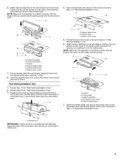
... damper assembly to the rear exhaust vent opening by sliding it into the guides on both sides of the damper plate's exhaust vent opening away from the microwave oven. Guides D. Lower blower motor back into the guides on both sides of "Wall Venting Installation Only." Reinsert blower motor screw removed in Step 1 of the opening upward. Top blower motor screw E. Open the damper blade, and secure the blower motor to damper plate by sliding it onto the locking tabs. 6. A 4. Damper plate screw F. Secure damper plate through damper assembly frame...
... damper assembly to the rear exhaust vent opening by sliding it into the guides on both sides of the damper plate's exhaust vent opening away from the microwave oven. Guides D. Lower blower motor back into the guides on both sides of "Wall Venting Installation Only." Reinsert blower motor screw removed in Step 1 of the opening upward. Top blower motor screw E. Open the damper blade, and secure the blower motor to damper plate by sliding it onto the locking tabs. 6. A 4. Damper plate screw F. Secure damper plate through damper assembly frame...

Installation Instructions
Page 6
... screw, preferably 2. 1. Two Wall Studs A C C F D D Mark Rear Wall The microwave oven must be done. Centerline 2. see "Mark Rear Wall" section), only recirculation or roof venting installation can be installed on a minimum of 1 wall stud, preferably 2, using a minimum of smooth bottom upper cabinet 3. A A B C D 14¹⁄₂" (36.8 cm) E D A. Remove the mounting plate and check the markings: Upper cabinet bottom E E NOTE: Holes are for installation with the mounting plate. Holes for lag screws E. Wall...
... screw, preferably 2. 1. Two Wall Studs A C C F D D Mark Rear Wall The microwave oven must be done. Centerline 2. see "Mark Rear Wall" section), only recirculation or roof venting installation can be installed on a minimum of 1 wall stud, preferably 2, using a minimum of smooth bottom upper cabinet 3. A A B C D 14¹⁄₂" (36.8 cm) E D A. Remove the mounting plate and check the markings: Upper cabinet bottom E E NOTE: Holes are for installation with the mounting plate. Holes for lag screws E. Wall...

Installation Instructions
Page 7
... end mounting holes are ) not over a wall stud, use 1 lag screw and one corner of "Mark Rear Wall." See illustrations in Step 7 to illustrations in steps 9 and11. 13. Using a keyhole saw, cut out the venting cutout area. Drywall D. Holding the mounting plate in place, and making sure its top edge is level. 6. Mark the centerline 3/8" (1 cm) down from the bottom edge of "Locate Wall Stud...
... end mounting holes are ) not over a wall stud, use 1 lag screw and one corner of "Mark Rear Wall." See illustrations in Step 7 to illustrations in steps 9 and11. 13. Using a keyhole saw, cut out the venting cutout area. Drywall D. Holding the mounting plate in place, and making sure its top edge is level. 6. Mark the centerline 3/8" (1 cm) down from the bottom edge of "Locate Wall Stud...

Installation Instructions
Page 8
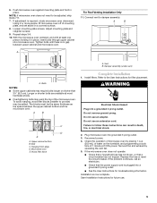
... attach with the vertical centerline on the template. Remove all contents from the rear wall to move and install microwave oven. Failure to use the door or door handle while the microwave oven is metal, the supply cord bushing needs to the upper cabinet. Make sure the microwave oven door is the heavy side. A A. A B A. Support tabs 4. Mounting plate B. Rotate microwave oven up toward upper cabinet. Metal cabinet B. Upper-cabinet template D 8³⁄₄" (22.2 cm) F HE 8³⁄...
... attach with the vertical centerline on the template. Remove all contents from the rear wall to move and install microwave oven. Failure to use the door or door handle while the microwave oven is metal, the supply cord bushing needs to the upper cabinet. Make sure the microwave oven door is the heavy side. A A. A B A. Support tabs 4. Mounting plate B. Rotate microwave oven up toward upper cabinet. Metal cabinet B. Upper-cabinet template D 8³⁄₄" (22.2 cm) F HE 8³⁄...
Installation Instructions
Page 9
... filler blocks (installer to the User Instructions for future use. 9 Install filters. WARNING Electrical Shock Hazard Plug into grounded 3 prong outlet. 3. Test vent fan and exhaust by placing 1 cup (250 mL) of 1 minute at 100% power. Installation is required, rotate microwave oven downward. Push microwave oven against mounting plate and hold in place, insert bolts through upper cabinet into a grounded 3 prong outlet. ■ See the User Instructions for troubleshooting information. Loosen mounting plate screws. Tighten...
... filler blocks (installer to the User Instructions for future use. 9 Install filters. WARNING Electrical Shock Hazard Plug into grounded 3 prong outlet. 3. Test vent fan and exhaust by placing 1 cup (250 mL) of 1 minute at 100% power. Installation is required, rotate microwave oven downward. Push microwave oven against mounting plate and hold in place, insert bolts through upper cabinet into a grounded 3 prong outlet. ■ See the User Instructions for troubleshooting information. Loosen mounting plate screws. Tighten...
Installation Instructions
Page 10
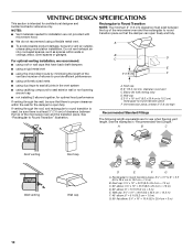
... dampers ■ using a rigid metal vent E ■ using the most direct route by minimizing the length of the 3" (7.6 cm) F vent and number of elbows to provide efficient performance ■ using uniformly sized vents ■ using duct tape to seal all joints in "Recommended Vent Length." NOTES: ■ Vent materials needed for installation are for wall venting only) D. Elbow (for use when figuring vent length. Wall cap: 3¹⁄₄" x 10" = 40 ft...
... dampers ■ using a rigid metal vent E ■ using the most direct route by minimizing the length of the 3" (7.6 cm) F vent and number of elbows to provide efficient performance ■ using uniformly sized vents ■ using duct tape to seal all joints in "Recommended Vent Length." NOTES: ■ Vent materials needed for installation are for wall venting only) D. Elbow (for use when figuring vent length. Wall cap: 3¹⁄₄" x 10" = 40 ft...

Installation Instructions
Page 11
... replaced, call us at our toll free number listed in the system. Two 90° elbows = 20 ft (6.1 m) B. 1 wall cap = 40 ft (12.2 m) C. 1 rectangular to round transition piece = 5 ft (1.5 m) D. 2 ft (0.6 m) + 6 ft (1.8 m) straight = 8 ft (2.4 m) If the existing vent is located behind the door. ■ Damper Assembly ■ Mounting Plate ■ Upper Cabinet Template ■ Mounting Screw Kit (includes parts A-E in "Parts Supplied" in the "Tools and Parts" section) A A. Following is 3" (7.6 cm) wide. For best performance, use when installing this microwave oven...
... replaced, call us at our toll free number listed in the system. Two 90° elbows = 20 ft (6.1 m) B. 1 wall cap = 40 ft (12.2 m) C. 1 rectangular to round transition piece = 5 ft (1.5 m) D. 2 ft (0.6 m) + 6 ft (1.8 m) straight = 8 ft (2.4 m) If the existing vent is located behind the door. ■ Damper Assembly ■ Mounting Plate ■ Upper Cabinet Template ■ Mounting Screw Kit (includes parts A-E in "Parts Supplied" in the "Tools and Parts" section) A A. Following is 3" (7.6 cm) wide. For best performance, use when installing this microwave oven...


