
Dimension Guide
Page 2
... REQUIREMENTS IMPORTANT: The range must be electrically grounded in accordance with local codes and ordinances, or in the absence of local codes, with cabinets. q Electronic ignition systems operate within the shaded area to change materials and specifications without notice. Cabinet door or hinges should not extend into the cutout. H. 3" (7.6 cm) distance...
... REQUIREMENTS IMPORTANT: The range must be electrically grounded in accordance with local codes and ordinances, or in the absence of local codes, with cabinets. q Electronic ignition systems operate within the shaded area to change materials and specifications without notice. Cabinet door or hinges should not extend into the cutout. H. 3" (7.6 cm) distance...
Installation Guide
Page 2
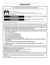
... the information in this gas cooking appliance resulting in this gas cooking appliance. If a gas leak is not followed exactly, a fire or explosion may cause ignition and combustion problems with this manual is detected, follow instructions. WARNING You can happen if the instructions are very important. All safety messages will follow...
... the information in this gas cooking appliance resulting in this gas cooking appliance. If a gas leak is not followed exactly, a fire or explosion may cause ignition and combustion problems with this manual is detected, follow instructions. WARNING You can happen if the instructions are very important. All safety messages will follow...
Installation Guide
Page 5
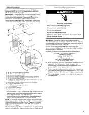
... the National Electrical Code, ANSI/NFPA 70 or Canadian Electrical Code, CSA C22.1. Check that a separate circuit serving only this range be provided. ■ Electronic ignition systems operate within the shaded area to countertop B. 13" (33.0 cm) upper cabinet depth C. 30" (76.2 cm) min. B D C A E F J I . 1¹⁄₂" (3.8 cm) min. Cabinet door...
... the National Electrical Code, ANSI/NFPA 70 or Canadian Electrical Code, CSA C22.1. Check that a separate circuit serving only this range be provided. ■ Electronic ignition systems operate within the shaded area to countertop B. 13" (33.0 cm) upper cabinet depth C. 30" (76.2 cm) min. B D C A E F J I . 1¹⁄₂" (3.8 cm) min. Cabinet door...
Installation Guide
Page 10
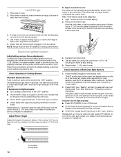
...than 4 seconds to "Off" and contact your dealer or authorized service company for assistance. "BAKE" scrolls down until range is displayed. Once the igniter is turned to light. If burners do not light properly: ■ Turn cooktop control knob to the "OFF" position. ■ Check that ...the range is lit it to the desired setting, a glow bar igniter heats and ignites the gas. A B 10 A. The first time a burner is plugged in the gas line. Then, after 3 seconds, "Preheating" scrolls in the ...
...than 4 seconds to "Off" and contact your dealer or authorized service company for assistance. "BAKE" scrolls down until range is displayed. Once the igniter is turned to light. If burners do not light properly: ■ Turn cooktop control knob to the "OFF" position. ■ Check that ...the range is lit it to the desired setting, a glow bar igniter heats and ignites the gas. A B 10 A. The first time a burner is plugged in the gas line. Then, after 3 seconds, "Preheating" scrolls in the ...

Installation Guide
Page 11
... to turn off the oven and contact your dealer or authorized service company for heat. Once the igniter is displayed. If burner does not light, press OFF/CANCEL to light the broil burner will glow. Read the Use and Care Guide or User ...
... to turn off the oven and contact your dealer or authorized service company for heat. Once the igniter is displayed. If burner does not light, press OFF/CANCEL to light the broil burner will glow. Read the Use and Care Guide or User ...

Installation Guide
Page 13
.... Do not overtighten. To Convert Oven Bake Burners To Convert Lower Oven Bake Burner: 1. A A B B A. Unscrew and remove the cover over and replace the plastic cover. Igniter and wires B. Bake burner screw 8. Bake burner cover 4. Orifice cover 13 A A A. Wing nut 6. Natural gas position B. 2. Gently set aside. 7.
.... Do not overtighten. To Convert Oven Bake Burners To Convert Lower Oven Bake Burner: 1. A A B B A. Unscrew and remove the cover over and replace the plastic cover. Igniter and wires B. Bake burner screw 8. Bake burner cover 4. Orifice cover 13 A A A. Wing nut 6. Natural gas position B. 2. Gently set aside. 7.
Installation Guide
Page 15
... a Phillips or Torx® screwdriver, remove the burner base. Burner base screws D. See the "LP Gas Orifice Spud Chart." 6. See "Make Gas Connection" and "Electronic Ignition System" sections. IMPORTANT: You may have a slightly yellow tip. See "Adjust Flame Height" in death or serious burns to adjust the "LO" setting for the... not operate range without anti-tip bracket installed and engaged. Natural Gas Conversion WARNING Tip Over Hazard A child or adult can result in the "Electronic Ignition System" section. B A C A. A B A.
... a Phillips or Torx® screwdriver, remove the burner base. Burner base screws D. See the "LP Gas Orifice Spud Chart." 6. See "Make Gas Connection" and "Electronic Ignition System" sections. IMPORTANT: You may have a slightly yellow tip. See "Adjust Flame Height" in death or serious burns to adjust the "LO" setting for the... not operate range without anti-tip bracket installed and engaged. Natural Gas Conversion WARNING Tip Over Hazard A child or adult can result in the "Electronic Ignition System" section. B A C A. A B A.

Installation Guide
Page 16
... cover B 4. Screw the regulator cap securely back into place. To Convert Gas Pressure Regulator 1. Wing nut 6. Gently set aside. 7. A A. Do not overtighten. Remove oven door. Igniter and wires B. B C A A A. Push the bake burner cover to the side. Regulator cap 3. Lift up and remove oven bake burner cover. 5. A B A. LP gas position...
... cover B 4. Screw the regulator cap securely back into place. To Convert Gas Pressure Regulator 1. Wing nut 6. Gently set aside. 7. A A. Do not overtighten. Remove oven door. Igniter and wires B. B C A A A. Push the bake burner cover to the side. Regulator cap 3. Lift up and remove oven bake burner cover. 5. A B A. LP gas position...

Installation Guide
Page 18
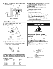
...Broil burner To Convert Surface Burners 1. Refer to adjust the "LO" setting for each burner. See "Make Gas Connection" and "Electronic Ignition System" sections. Place the broil burner on the broil burner orifice hood. LP gas orifice spud Use the following chart for correct Natural gas... nut driver to remove. 3. Burner base screws B. A C B D A A. Insert the broil burner locator pin in the hole in the "Electronic Ignition System" section. 18 A B A. Turn the green Number 0.037 LP gas broil burner orifice hood counterclockwise to help hold the LP gas orifice spud in...
...Broil burner To Convert Surface Burners 1. Refer to adjust the "LO" setting for each burner. See "Make Gas Connection" and "Electronic Ignition System" sections. Place the broil burner on the broil burner orifice hood. LP gas orifice spud Use the following chart for correct Natural gas... nut driver to remove. 3. Burner base screws B. A C B D A A. Insert the broil burner locator pin in the hole in the "Electronic Ignition System" section. 18 A B A. Turn the green Number 0.037 LP gas broil burner orifice hood counterclockwise to help hold the LP gas orifice spud in...

Use & Care Guide
Page 5
...specialist. HI ■ Start food cooking. ■ Bring liquid to follow these instructions can result in death or fire. Electric igniters automatically light the surface burners when control knobs are ideal for use or (on the valve shaft. All the surface burners will produce... turned to LIGHT. Alignment pins D. See the "Gas Conversions" section of the Installation Instructions for a clicking sound. If the burner does not ignite, listen for details on the grate. Burner cap B. Left rear control knob B C D E C. SETTING RECOMMENDED USE LIGHT ■ Light ...
...specialist. HI ■ Start food cooking. ■ Bring liquid to follow these instructions can result in death or fire. Electric igniters automatically light the surface burners when control knobs are ideal for use or (on the valve shaft. All the surface burners will produce... turned to LIGHT. Alignment pins D. See the "Gas Conversions" section of the Installation Instructions for a clicking sound. If the burner does not ignite, listen for details on the grate. Burner cap B. Left rear control knob B C D E C. SETTING RECOMMENDED USE LIGHT ■ Light ...

Use & Care Guide
Page 6
..., do not use pans or metal utensils on the burner. Locating tabs 4. NOTE: When properly installed, the bottom of the griddle will help avoid poor ignition and uneven flames. Keep this area free of soil and do not use nonstick cooking sprays. 6 Replace the burner cap, making sure the alignment pins...
..., do not use pans or metal utensils on the burner. Locating tabs 4. NOTE: When properly installed, the bottom of the griddle will help avoid poor ignition and uneven flames. Keep this area free of soil and do not use nonstick cooking sprays. 6 Replace the burner cap, making sure the alignment pins...


