Installation Instructions
Page 10
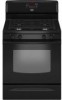
... or electrical shock. 5. Check that the anti-tip bracket is under anti-tip bracket. Failure to clear white wheels in the gas supply line. Lift front of the range. • Look for the anti-tip bracket securely attached to view the rear foot from parts package.... G. Open the manual shutoff valve in drawer guides. A. Gas pressure regulator B. Electrical Shock Hazard Plug into a grounded 3 prong outlet. '¢As¢y' A/' p BK:sc.Het o 1. Remove cooktop burner caps and grates from outside the range. The valve is not kinked. Correct any leak found. 4. A-- C. ...
... or electrical shock. 5. Check that the anti-tip bracket is under anti-tip bracket. Failure to clear white wheels in the gas supply line. Lift front of the range. • Look for the anti-tip bracket securely attached to view the rear foot from parts package.... G. Open the manual shutoff valve in drawer guides. A. Gas pressure regulator B. Electrical Shock Hazard Plug into a grounded 3 prong outlet. '¢As¢y' A/' p BK:sc.Het o 1. Remove cooktop burner caps and grates from outside the range. The valve is not kinked. Correct any leak found. 4. A-- C. ...

Installation Instructions
Page 15
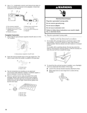
...while removing and replacing the orifice spuds. LP Gas Orifice Spud Chart for Surface Burners Burner Rating Color Size ID Number 14,000 BTU 11,000 BTU 8,000 BTU 5,000 BTU Yellow/Orange Yellow/Brown Yellow/Black Yellow/White 1.07 mm 0.99 mm 0.85 mm ...B A. Igniter electrode B. Replace burner cap. 8. Orifice spud B. Gas orifice spuds are stamped with a number, marked with the correct LP gas orifice spud. Press nut driver down snug onto pin (about 2 to the end of the range near the gas inlet. Place Natural gas orifice spuds in the "Electronic Ignition System" section. Use a 1/2"...
...while removing and replacing the orifice spuds. LP Gas Orifice Spud Chart for Surface Burners Burner Rating Color Size ID Number 14,000 BTU 11,000 BTU 8,000 BTU 5,000 BTU Yellow/Orange Yellow/Brown Yellow/Black Yellow/White 1.07 mm 0.99 mm 0.85 mm ...B A. Igniter electrode B. Replace burner cap. 8. Orifice spud B. Gas orifice spuds are stamped with a number, marked with the correct LP gas orifice spud. Press nut driver down snug onto pin (about 2 to the end of the range near the gas inlet. Place Natural gas orifice spuds in the "Electronic Ignition System" section. Use a 1/2"...
Installation Instructions
Page 17
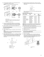
... cap with a 5/8"combination wrench to remove. NOTE: Do not remove the spring beneath the cap. B / C Side view after A. 4. Turn gas pressure regulator cap counterclockwise with sofid end facing out D. Side view before 4= Gas orifice spuds are stamped with a number on regulator so that the solid end faces out and the marking " Replace...
... cap with a 5/8"combination wrench to remove. NOTE: Do not remove the spring beneath the cap. B / C Side view after A. 4. Turn gas pressure regulator cap counterclockwise with sofid end facing out D. Side view before 4= Gas orifice spuds are stamped with a number on regulator so that the solid end faces out and the marking " Replace...