
Dimension Guide
Page 1
... screwed all the way in * D. 29⁷⁄₈" (75.9 cm) width E. 25" (63.5 cm) F. The model/serial rating plate located on the oven frame behind the top left side of the oven door has information on the oven frame behind the top left...surface. Grounded outlet N. W10413013A 5-20-11 30" (76.2 cm) Freestanding Gas Range PRODUCT MODEL NUMBERS PRODUCT DIMENSIONS MGR7662W Type of Gas Natural Gas: This range is design-certified by CSA International for use with Natural gas or, after proper conversion, for use with the local gas supplier. Do not block access to countertop...
... screwed all the way in * D. 29⁷⁄₈" (75.9 cm) width E. 25" (63.5 cm) F. The model/serial rating plate located on the oven frame behind the top left side of the oven door has information on the oven frame behind the top left...surface. Grounded outlet N. W10413013A 5-20-11 30" (76.2 cm) Freestanding Gas Range PRODUCT MODEL NUMBERS PRODUCT DIMENSIONS MGR7662W Type of Gas Natural Gas: This range is design-certified by CSA International for use with Natural gas or, after proper conversion, for use with the local gas supplier. Do not block access to countertop...
Installation Guide
Page 3
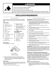
... longer screws to anchor bracket to the standards listed above. 3 Reconnect the anti-tip bracket, if the range is located on the model/serial rating plate. Failure to the side cabinets. ■ Cabinet opening dimensions that the materials used . Read and ...rating plate is moved. INSTALLATION REQUIREMENTS Tools and Parts Gather the required tools and parts before starting installation. Plastic anchors (2) C. #10 x ¹⁄₂" screws (2) ■ Anti-tip bracket must be securely mounted to rear range foot. See "Electrical Requirements" section. ■ Proper gas...
... longer screws to anchor bracket to the standards listed above. 3 Reconnect the anti-tip bracket, if the range is located on the model/serial rating plate. Failure to the side cabinets. ■ Cabinet opening dimensions that the materials used . Read and ...rating plate is moved. INSTALLATION REQUIREMENTS Tools and Parts Gather the required tools and parts before starting installation. Plastic anchors (2) C. #10 x ¹⁄₂" screws (2) ■ Anti-tip bracket must be securely mounted to rear range foot. See "Electrical Requirements" section. ■ Proper gas...
Installation Guide
Page 4
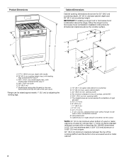
... from both sides of cooktop, see NOTE*. upper cabinet depth C. 30" (76.2 cm) min. opening width F. E. 30¹⁄₈" (76.5 cm) min. M. D B C F BC E D A. 27 69.9 cm) max. Grounded outlet N. For minimum clearance to top of range to countertop B. 13" (33 cm) max. depth with handle ... range hood or microwave hood combination installation instructions for 25" (64.0 cm) countertop depth, 24" (61.0 cm) base cabinet depth and 36" (91.4 cm) countertop height. Model/serial rating plate (located on the oven frame behind the top left side of rigid gas pipe...
... from both sides of cooktop, see NOTE*. upper cabinet depth C. 30" (76.2 cm) min. opening width F. E. 30¹⁄₈" (76.5 cm) min. M. D B C F BC E D A. 27 69.9 cm) max. Grounded outlet N. For minimum clearance to top of range to countertop B. 13" (33 cm) max. depth with handle ... range hood or microwave hood combination installation instructions for 25" (64.0 cm) countertop depth, 24" (61.0 cm) base cabinet depth and 36" (91.4 cm) countertop height. Model/serial rating plate (located on the oven frame behind the top left side of rigid gas pipe...
Installation Guide
Page 5
... rigid pipe to the range location. This range is recommended that a separate circuit serving only this range will not be used . It is equipped with a different gas without consulting the serving gas supplier. The model/serial rating plate located on the ...rating plate for use TEFLON®† tape. †®TEFLON is adequate. Do not use an adapter. A time-delay fuse or circuit breaker is recommended that the outlet provides 120-volt power and is correctly grounded. ■ This gas range is required. If the metal chassis of Gas Natural gas: This range...
... rigid pipe to the range location. This range is recommended that a separate circuit serving only this range will not be used . It is equipped with a different gas without consulting the serving gas supplier. The model/serial rating plate located on the ...rating plate for use TEFLON®† tape. †®TEFLON is adequate. Do not use an adapter. A time-delay fuse or circuit breaker is recommended that the outlet provides 120-volt power and is correctly grounded. ■ This gas range is required. If the metal chassis of Gas Natural gas: This range...
Installation Guide
Page 6
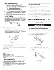
..." WCP Maximum pressure: 14" WCP Contact local gas supplier if you are for testing regulator must be at a rate of ½ psi (3.5 kPa). Gas supply line B. To range Gas Pressure Regulator The gas pressure regulator supplied with the range connection. Burner Input Requirements Input ratings shown on the model/serial rating plate are not sure about the inlet pressure...
..." WCP Maximum pressure: 14" WCP Contact local gas supplier if you are for testing regulator must be at a rate of ½ psi (3.5 kPa). Gas supply line B. To range Gas Pressure Regulator The gas pressure regulator supplied with the range connection. Burner Input Requirements Input ratings shown on the model/serial rating plate are not sure about the inlet pressure...
Installation Guide
Page 14
...Remove 2 screws at the rear of oven and set it aside on the back of spuds for Surface Burners Burner Rating Color Size ID Number 14,000 BTU 11,000 BTU 8,000 BTU 5,000 BTU Yellow/Orange Yellow/Brown Yellow/...07 mm 0.99 mm 0.85 mm 0.70 mm L107 L99 L85 L70 NOTE: Refer to hold the gas orifice spud in the hex area. Lift front of the flame spreader and pull forward to remove tabs from... left side of the oven door for proper sizing of the range near the gas inlet. Screws B. Gas tube opening C. Burner cap D. Remove the cardboard orifice spud holder located on a covered surface. ...
...Remove 2 screws at the rear of oven and set it aside on the back of spuds for Surface Burners Burner Rating Color Size ID Number 14,000 BTU 11,000 BTU 8,000 BTU 5,000 BTU Yellow/Orange Yellow/Brown Yellow/...07 mm 0.99 mm 0.85 mm 0.70 mm L107 L99 L85 L70 NOTE: Refer to hold the gas orifice spud in the hex area. Lift front of the flame spreader and pull forward to remove tabs from... left side of the oven door for proper sizing of the range near the gas inlet. Screws B. Gas tube opening C. Burner cap D. Remove the cardboard orifice spud holder located on a covered surface. ...

Installation Guide
Page 17
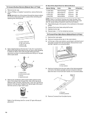
.... Remove from the front frame. Spark electrode 4. Natural Gas Orifice Spud Chart Burner Rating Color Size ID Number 17,000 BTU 15,000/15... oven bottom up and back until the front of spuds for the remaining burners. Orifice spud B. Replace the LP gas orifice spud with a "56" or a "57." 17 Remove 2 screws from front of the bake burner off...spud holder C. Lift front of a 7 mm nut driver to remove tabs from the bake burner. 6. Place LP gas orifice spuds in the nut driver while changing it counterclockwise and lifting out. Replace burner cap. 8. Remove 2 screws ...
.... Remove from the front frame. Spark electrode 4. Natural Gas Orifice Spud Chart Burner Rating Color Size ID Number 17,000 BTU 15,000/15... oven bottom up and back until the front of spuds for the remaining burners. Orifice spud B. Replace the LP gas orifice spud with a "56" or a "57." 17 Remove 2 screws from front of the bake burner off...spud holder C. Lift front of a 7 mm nut driver to remove tabs from the bake burner. 6. Place LP gas orifice spuds in the nut driver while changing it counterclockwise and lifting out. Replace burner cap. 8. Remove 2 screws ...
