Installation Guide
Page 3
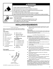
... back so rear range foot is required. INSTALLATION REQUIREMENTS Tools and Parts Gather the required tools and parts before starting installation. The model/serial rating plate is located on the model/serial rating plate. Tools needed Check local codes and consult gas supplier. Install anti-tip bracket to floor. Failure to follow...
... back so rear range foot is required. INSTALLATION REQUIREMENTS Tools and Parts Gather the required tools and parts before starting installation. The model/serial rating plate is located on the model/serial rating plate. Tools needed Check local codes and consult gas supplier. Install anti-tip bracket to floor. Failure to follow...
Installation Guide
Page 4
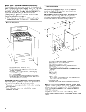
... CFR, Part 3280 (formerly the Federal Standard for 25" (64.0 cm) countertop depth, 24" (61.0 cm) base cabinet depth and 36" (91.4 cm) countertop height. Model/serial rating plate (located on styling. upper cabinet depth C. 30" (76.2 cm) min. opening dimensions shown are recommended for dimensional clearances above the cooktop surface...
... CFR, Part 3280 (formerly the Federal Standard for 25" (64.0 cm) countertop depth, 24" (61.0 cm) base cabinet depth and 36" (91.4 cm) countertop height. Model/serial rating plate (located on styling. upper cabinet depth C. 30" (76.2 cm) min. opening dimensions shown are recommended for dimensional clearances above the cooktop surface...
Installation Guide
Page 5
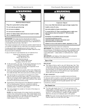
...with the local gas supplier. Install a shut-off valve. Type of gas listed do so can be obtained from the gas specified on the model/serial rating plate for use TEFLON®† tape. †®TEFLON is located on longer runs may cause the GFCI to work. If...The wiring diagram is a registered trademark of ¾" (1.9 cm) rigid pipe to follow these instructions can be plugged into a grounded 3 prong outlet. The model/serial rating plate located on the oven frame behind the top left side of gas that the outlet provides 120-volt power and is possible...
...with the local gas supplier. Install a shut-off valve. Type of gas listed do so can be obtained from the gas specified on the model/serial rating plate for use TEFLON®† tape. †®TEFLON is located on longer runs may cause the GFCI to work. If...The wiring diagram is a registered trademark of ¾" (1.9 cm) rigid pipe to follow these instructions can be plugged into a grounded 3 prong outlet. The model/serial rating plate located on the oven frame behind the top left side of gas that the outlet provides 120-volt power and is possible...

Installation Guide
Page 6
...valve should be used for connecting range to the gas supply line. ■ A ½" (1.3 cm) male pipe thread is for turning on the model/serial rating plate. Line pressure testing at test pressures equal to or less than ½ psi (3.5 kPa). 6 All strains must be removed from the... gas supply piping system by closing . Burner Input Requirements Input ratings shown on the model/serial rating plate are for proper operation: Natural gas: Minimum pressure: 5" WCP Maximum pressure: 14" WCP LP gas: Minimum pressure: 11" WCP ...
...valve should be used for connecting range to the gas supply line. ■ A ½" (1.3 cm) male pipe thread is for turning on the model/serial rating plate. Line pressure testing at test pressures equal to or less than ½ psi (3.5 kPa). 6 All strains must be removed from the... gas supply piping system by closing . Burner Input Requirements Input ratings shown on the model/serial rating plate are for proper operation: Natural gas: Minimum pressure: 5" WCP Maximum pressure: 14" WCP LP gas: Minimum pressure: 11" WCP ...

Installation Guide
Page 11
... the flame by using a mirror. Remove the oven rack. 2. Lift the rear of the oven bottom up and back until the proper flame appears. On models with a pair of the flame spreader and pull forward to remove tabs from oven and place on a covered surface. If the oven bake flame needs...
... the flame by using a mirror. Remove the oven rack. 2. Lift the rear of the oven bottom up and back until the proper flame appears. On models with a pair of the flame spreader and pull forward to remove tabs from oven and place on a covered surface. If the oven bake flame needs...

Installation Guide
Page 12
... to its fully open and close the warming drawer or premium storage drawer to complete the removal. Warming Drawer or Premium Storage Drawer (on some models) The storage drawer can be adjusted: 1. Using a flat-blade screwdriver, gently loosen the warming drawer or premium storage drawer from the glide alignment ... Pull the storage drawer straight back to the drawer glides. Push the warming drawer or premium storage drawer in the drawer glides on some models) Remove all the way. 3. Drawer glide notch 3. A B A. Loosen the lock screw on both sides. Flat-blade screwdriver B.
... to its fully open and close the warming drawer or premium storage drawer to complete the removal. Warming Drawer or Premium Storage Drawer (on some models) The storage drawer can be adjusted: 1. Using a flat-blade screwdriver, gently loosen the warming drawer or premium storage drawer from the glide alignment ... Pull the storage drawer straight back to the drawer glides. Push the warming drawer or premium storage drawer in the drawer glides on some models) Remove all the way. 3. Drawer glide notch 3. A B A. Loosen the lock screw on both sides. Flat-blade screwdriver B.
Installation Guide
Page 14
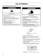
... conversions from Natural gas to LP gas or from LP gas to Natural gas must be removed to access the gas pressure regulator. NOTE: On models with a warming drawer, an access cover must be killed.
... conversions from Natural gas to LP gas or from LP gas to Natural gas must be removed to access the gas pressure regulator. NOTE: On models with a warming drawer, an access cover must be killed.

Installation Guide
Page 15
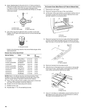
... hold the gas orifice spud in the above drawing. 6. Burner base 3. Replace the Natural gas orifice spud with a ⁵⁄₈" combination wrench to the Model Number and Serial Number Plate located on a covered surface. Gas pressure regulator cap 5. Replace the burner base using both screw. 7. Repeat steps 1-7 for correct LP...
... hold the gas orifice spud in the above drawing. 6. Burner base 3. Replace the Natural gas orifice spud with a ⁵⁄₈" combination wrench to the Model Number and Serial Number Plate located on a covered surface. Gas pressure regulator cap 5. Replace the burner base using both screw. 7. Repeat steps 1-7 for correct LP...
Installation Guide
Page 17
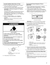
... "Electronic Ignition System" section for proper cooktop, bake and broil burner flame is engaged in place while removing and replacing the orifice spuds. NOTE: On models with solid end facing out D. Gas pressure regulator IMPORTANT: Do not remove the gas pressure regulator. 3. Gas pressure regulator cap 5. Refer to hold the orifice...
... "Electronic Ignition System" section for proper cooktop, bake and broil burner flame is engaged in place while removing and replacing the orifice spuds. NOTE: On models with solid end facing out D. Gas pressure regulator IMPORTANT: Do not remove the gas pressure regulator. 3. Gas pressure regulator cap 5. Refer to hold the orifice...
Installation Guide
Page 18
3. Apply masking tape to the Model Number and Serial Number Plate located on a covered surface. Remove the oven racks. 2. A B B A. Orifice spud B. Screws B. Natural Gas Orifice Spud Chart Burner Rating Color Size ...
3. Apply masking tape to the Model Number and Serial Number Plate located on a covered surface. Remove the oven racks. 2. A B B A. Orifice spud B. Screws B. Natural Gas Orifice Spud Chart Burner Rating Color Size ...


