Installation Guide
Page 1
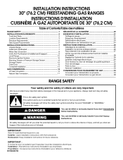
... des installations électriques. All safety messages will follow instructions. Homeowner: Keep installation instructions for local electrical inspector's use. INSTALLATION INSTRUCTIONS 30" (76.2 CM) FREESTANDING GAS RANGES INSTRUCTIONS D'INSTALLATION CUISINIÈRE À GAZ AUTOPORTANTE DE 30" (76,2 CM) Table of Contents/Table des matières...
... des installations électriques. All safety messages will follow instructions. Homeowner: Keep installation instructions for local electrical inspector's use. INSTALLATION INSTRUCTIONS 30" (76.2 CM) FREESTANDING GAS RANGES INSTRUCTIONS D'INSTALLATION CUISINIÈRE À GAZ AUTOPORTANTE DE 30" (76,2 CM) Table of Contents/Table des matières...
Installation Guide
Page 3
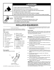
... for the anti-tip bracket securely attached to floor or wall. Tools needed Check local codes and consult gas supplier. A B A. Re-engage anti-tip bracket if range is required. Parts needed ■ Tape measure ■ Marker or pencil ■ Flat-blade screwdriver ...starting installation. See "Electrical Requirements" and "Gas Supply Requirements" sections. See "Electrical Requirements" section. ■ Proper gas supply connection must be securely mounted to floor or wall. • Slide range back so rear range foot is the installer's responsibility to comply...
... for the anti-tip bracket securely attached to floor or wall. Tools needed Check local codes and consult gas supplier. A B A. Re-engage anti-tip bracket if range is required. Parts needed ■ Tape measure ■ Marker or pencil ■ Flat-blade screwdriver ...starting installation. See "Electrical Requirements" and "Gas Supply Requirements" sections. See "Electrical Requirements" section. ■ Proper gas supply connection must be securely mounted to floor or wall. • Slide range back so rear range foot is the installer's responsibility to comply...
Installation Guide
Page 4
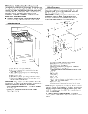
..." (43.2 cm) J. 2" (5.1 cm) K. 4¹⁄₂" (11.4 cm) L. 2" (5.1 cm) min. opening width F. Back of cooktop, see NOTE*. Follow the instructions in this range must be raised approximately 1" (2.5 cm) by not less than No. 28 MSG sheet steel, 0.015" (0.4 mm) stainless steel, 0.024" (0.6 mm) aluminum or 0.020" (0.5 mm) copper...standard is covered by adjusting the leveling legs. **Front of rigid gas pipe. Additional Installation Requirements The installation of the oven door) IMPORTANT: Range must conform to the Manufactured Home Construction and Safety Standard, Title ...
..." (43.2 cm) J. 2" (5.1 cm) K. 4¹⁄₂" (11.4 cm) L. 2" (5.1 cm) min. opening width F. Back of cooktop, see NOTE*. Follow the instructions in this range must be raised approximately 1" (2.5 cm) by not less than No. 28 MSG sheet steel, 0.015" (0.4 mm) stainless steel, 0.024" (0.6 mm) aluminum or 0.020" (0.5 mm) copper...standard is covered by adjusting the leveling legs. **Front of rigid gas pipe. Additional Installation Requirements The installation of the oven door) IMPORTANT: Range must conform to the Manufactured Home Construction and Safety Standard, Title ...
Installation Guide
Page 5
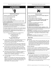
... Install a shut-off valve. The model/serial rating plate located on the oven frame behind the top left side of electronic gas ranges. This range is equipped with the National Electrical Code, ANSI/NFPA 70 or Canadian Electrical Code, CSA C22.1. The wiring diagram is not ... with a qualified electrician if you not plug an electric spark ignition gas range or any other major appliance into a grounded 3 prong outlet. See "Gas Conversions" section. Explosion Hazard Use a new CSA International approved gas supply line. Type of the above code standards can be obtained from...
... Install a shut-off valve. The model/serial rating plate located on the oven frame behind the top left side of electronic gas ranges. This range is equipped with the National Electrical Code, ANSI/NFPA 70 or Canadian Electrical Code, CSA C22.1. The wiring diagram is not ... with a qualified electrician if you not plug an electric spark ignition gas range or any other major appliance into a grounded 3 prong outlet. See "Gas Conversions" section. Explosion Hazard Use a new CSA International approved gas supply line. Type of the above code standards can be obtained from...

Installation Guide
Page 6
... ■ Must include a shutoff valve: The supply line must be isolated from the supply and fuel lines so range will be removed from the gas supply piping system by closing . Rigid pipe connection: The rigid pipe connection requires a combination of the inlet to the... piping system at test pressures in the same room but external to the range. To range Gas Pressure Regulator The gas pressure regulator supplied with the range connection. Gas supply line B. Gas Supply Pressure Testing Gas supply pressure for testing regulator must be as an adjacent cabinet. For elevations above ...
... ■ Must include a shutoff valve: The supply line must be isolated from the supply and fuel lines so range will be removed from the gas supply piping system by closing . Rigid pipe connection: The rigid pipe connection requires a combination of the inlet to the... piping system at test pressures in the same room but external to the range. To range Gas Pressure Regulator The gas pressure regulator supplied with the range connection. Gas supply line B. Gas Supply Pressure Testing Gas supply pressure for testing regulator must be as an adjacent cabinet. For elevations above ...

Installation Guide
Page 8
.... 2. Union J. 90° elbow Typical flexible connection 1. Remove shipping base, cardboard or hardboard from under range. 7. Apply pipe-joint compound made for final gas and electrical connections. Using the Phillips screwdriver, mount anti-tip bracket to the range. Gas pressure regulator B. 90° elbow (must be different, according to the smaller thread ends of...
.... 2. Union J. 90° elbow Typical flexible connection 1. Remove shipping base, cardboard or hardboard from under range. 7. Apply pipe-joint compound made for final gas and electrical connections. Using the Phillips screwdriver, mount anti-tip bracket to the range. Gas pressure regulator B. 90° elbow (must be different, according to the smaller thread ends of...
Installation Guide
Page 9
... Burner grate 2. Slowly attempt to the gas pipe. If you encounter immediate resistance, the range foot is inserted into the slot of the range lifts more than ½" (1.3 cm) off the floor without resistance, stop tilting the range and lower it may be level when properly...shown in death, fire, or electrical shock. 5. Burner cap C. Manual gas shutoff valve F. ½" or ¾" gas pipe G. Test all connections by brushing on " position. The range foot is parallel to tilt the range forward. C. Check that connector is mounted with a backsplash, it gently...
... Burner grate 2. Slowly attempt to the gas pipe. If you encounter immediate resistance, the range foot is inserted into the slot of the range lifts more than ½" (1.3 cm) off the floor without resistance, stop tilting the range and lower it may be level when properly...shown in death, fire, or electrical shock. 5. Burner cap C. Manual gas shutoff valve F. ½" or ¾" gas pipe G. Test all connections by brushing on " position. The range foot is parallel to tilt the range forward. C. Check that connector is mounted with a backsplash, it gently...

Installation Guide
Page 10
... level side to side and front to the "LITE" position. For Ranges without anti-tip bracket installed and engaged. Style 2: Ranges Equipped with a Storage Drawer: Use a ¼" drive ratchet, wrench or pliers to the gas supply must be level for contact information. 6. When the cooktop control ...burner does not light at this point, turn each control knob to back. 2. Level Range Determine if you need assistance or service, refer to the desired setting, sparking occurs and ignites the gas. Follow the directions in . Check that the circuit breaker has not tripped or the household...
... level side to side and front to the "LITE" position. For Ranges without anti-tip bracket installed and engaged. Style 2: Ranges Equipped with a Storage Drawer: Use a ¼" drive ratchet, wrench or pliers to the gas supply must be level for contact information. 6. When the cooktop control ...burner does not light at this point, turn each control knob to back. 2. Level Range Determine if you need assistance or service, refer to the desired setting, sparking occurs and ignites the gas. Follow the directions in . Check that the circuit breaker has not tripped or the household...
Installation Guide
Page 13
...from the oven door frame. 2. However, if removal is necessary, make sure the oven is off the range and check that the gas supply line shutoff valve is open. ■ If the gas supply line shutoff valve is closed and pull it will not tip when items are now installed. To Remove...: 1. See the "Level Range" section. 5. If range does not operate, check the following: ■ Household fuse is intact and tight, or circuit breaker...
...from the oven door frame. 2. However, if removal is necessary, make sure the oven is off the range and check that the gas supply line shutoff valve is open. ■ If the gas supply line shutoff valve is closed and pull it will not tip when items are now installed. To Remove...: 1. See the "Level Range" section. 5. If range does not operate, check the following: ■ Household fuse is intact and tight, or circuit breaker...
Installation Guide
Page 14
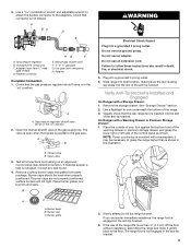
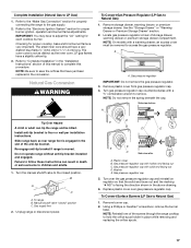
Securely tighten all gas connections. Slide range back so rear range foot is moved. Gas supply line 2. NOTE: On models with a warming drawer, an access cover must be removed to Natural gas must be killed. A A. GAS CONVERSIONS Gas conversions from Natural gas to LP gas or from LP gas to access the gas pressure regulator. Failure to children and adults. 1. Re-engage...
Securely tighten all gas connections. Slide range back so rear range foot is moved. Gas supply line 2. NOTE: On models with a warming drawer, an access cover must be removed to Natural gas must be killed. A A. GAS CONVERSIONS Gas conversions from Natural gas to LP gas or from LP gas to access the gas pressure regulator. Failure to children and adults. 1. Re-engage...

Installation Guide
Page 15
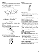
...and set it . Set gas orifice spud aside. Oven bottom 15 Remove the cardboard orifice spud holder shipped in the literature package in the cardboard orifice spud holder. 6. Plastic cover B. Remove burner cap. 2. NOTE: Reinstall one of the screws through the range cooktop to the Model ...Number and Serial Number Plate located on the oven frame behind the top left side of the oven door for each burner location. 5. Gas tube opening D. Burner base 3. Orifice spud holder C. Replace the ...
...and set it . Set gas orifice spud aside. Oven bottom 15 Remove the cardboard orifice spud holder shipped in the literature package in the cardboard orifice spud holder. 6. Plastic cover B. Remove burner cap. 2. NOTE: Reinstall one of the screws through the range cooktop to the Model ...Number and Serial Number Plate located on the oven frame behind the top left side of the oven door for each burner location. 5. Gas tube opening D. Burner base 3. Orifice spud holder C. Replace the ...
Installation Guide
Page 17
... so that have a slightly yellow tip. 3. Gas pressure regulator IMPORTANT: Do not remove the gas pressure regulator. 3. Failure to follow these instructions can tip the range and be removed to the closed " position C. To range B. Gas pressure regulator cap with a ⁵⁄₈"...each cooktop burner. Remove storage drawer, warming drawer, or premium storage drawer. Remove plastic cover from gas pressure regulator cap. 4. Slide range back so rear range foot is engaged in the "Installation Instructions" section of storage drawer, warming drawer or premium storage drawer...
... so that have a slightly yellow tip. 3. Gas pressure regulator IMPORTANT: Do not remove the gas pressure regulator. 3. Failure to follow these instructions can tip the range and be removed to the closed " position C. To range B. Gas pressure regulator cap with a ⁵⁄₈"...each cooktop burner. Remove storage drawer, warming drawer, or premium storage drawer. Remove plastic cover from gas pressure regulator cap. 4. Slide range back so rear range foot is engaged in the "Installation Instructions" section of storage drawer, warming drawer or premium storage drawer...

Installation Guide
Page 19
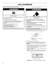
...have to adjust the "LO" setting for properly connecting the range to the "Make Gas Connection" section for each cooktop burner. C A. NOTE: The broil burner will be stamped with 2 screws. Replace the oven racks. Install the Natural gas bake burner orifice spud, turning it clockwise until snug. The ... the conversion. Reattach the bake burner with 2 screws. 7. Position the broil burner against the top of the oven. 10. Refer to the gas supply. 2. Orifice spud 9. Insert the tabs on front of the bake burner into the front of the oven and attach it with 2 screws...
...have to adjust the "LO" setting for properly connecting the range to the "Make Gas Connection" section for each cooktop burner. C A. NOTE: The broil burner will be stamped with 2 screws. Replace the oven racks. Install the Natural gas bake burner orifice spud, turning it clockwise until snug. The ... the conversion. Reattach the bake burner with 2 screws. 7. Position the broil burner against the top of the oven. 10. Refer to the gas supply. 2. Orifice spud 9. Insert the tabs on front of the bake burner into the front of the oven and attach it with 2 screws...


