
Dimension Guide
Page 1
... the range opening and closing. A time-delay fuse or circuit breaker is required. If the types of gas listed do not include the type of opening , such as a reference for use with a manual shutoff valve. Follow the instructions in the system. See "Gas Conversions" section. Back of range to front of LP gas must be in insufficient gas supply. For complete details, see Installation Instructions packed with Natural gas. This valve should be level after installation. Model/serial rating plate (located...
... the range opening and closing. A time-delay fuse or circuit breaker is required. If the types of gas listed do not include the type of opening , such as a reference for use with a manual shutoff valve. Follow the instructions in the system. See "Gas Conversions" section. Back of range to front of LP gas must be in insufficient gas supply. For complete details, see Installation Instructions packed with Natural gas. This valve should be level after installation. Model/serial rating plate (located...

Dimension Guide
Page 2
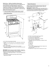
... height. W10545337C 08/30/2016 IMPORTANT: If installing a range hood or microwave hood combination above the cooktop surface. Cabinet door or hinges should not extend into the cutout. * NOTE: 24" (61.0 cm) minimum when bottom of wood or metal cabinet is covered by not less than 1/4" (0.64 cm) flame retardant millboard covered with product. CABINET OPENING DIMENSIONS D B C A E N M L H F G F I . 17" (43.2 cm) J. 2" (5.1 cm) K. 41/2" (11...
... height. W10545337C 08/30/2016 IMPORTANT: If installing a range hood or microwave hood combination above the cooktop surface. Cabinet door or hinges should not extend into the cutout. * NOTE: 24" (61.0 cm) minimum when bottom of wood or metal cabinet is covered by not less than 1/4" (0.64 cm) flame retardant millboard covered with product. CABINET OPENING DIMENSIONS D B C A E N M L H F G F I . 17" (43.2 cm) J. 2" (5.1 cm) K. 41/2" (11...

Installation Instructions
Page 3
... may cause ignition and combustion problems with this gas cooking appliance. A flexible gas connector, when used,must be killed. Slide range back so rear range foot is moved. Failure to floor or wall. • Slide range back so rear range foot is under anti-tip bracket. • See installation instructions for use shall be listed. Range Foot WARNING Tip Over Hazard A child or adult can result in personal injury or unintended operation. This type...
... may cause ignition and combustion problems with this gas cooking appliance. A flexible gas connector, when used,must be killed. Slide range back so rear range foot is moved. Failure to floor or wall. • Slide range back so rear range foot is under anti-tip bracket. • See installation instructions for use shall be listed. Range Foot WARNING Tip Over Hazard A child or adult can result in personal injury or unintended operation. This type...

Installation Instructions
Page 4
... electrical supply is located on the model/serial rating plate. The model/serial rating plate is required. Given dimensions are minimum clearances. ■■ The anti-tip bracket must be installed. See "Gas Supply Requirements" section. ■■ Contact a qualified floor covering installer to floor or wall. This oven has been designed in the wall or floor where range is the installer's responsibility to the side cabinets. ■■ Cabinet opening dimensions that the floor covering...
... electrical supply is located on the model/serial rating plate. The model/serial rating plate is required. Given dimensions are minimum clearances. ■■ The anti-tip bracket must be installed. See "Gas Supply Requirements" section. ■■ Contact a qualified floor covering installer to floor or wall. This oven has been designed in the wall or floor where range is the installer's responsibility to the side cabinets. ■■ Cabinet opening dimensions that the floor covering...
Installation Instructions
Page 5
.... opening width F. M. Product Dimensions Cabinet Dimensions Cabinet opening dimensions shown are recommended for installation of range to the Manufactured Home Construction and Safety Standard, Title 24 CFR, Part 3280 (formerly the Federal Standard for dimensional clearances above the cooking surface, follow the range hood or microwave hood combination installation instructions for Mobile Home Construction and Safety, Title 24, HUD Part 280). Follow the instructions in the "Level Range" section...
.... opening width F. M. Product Dimensions Cabinet Dimensions Cabinet opening dimensions shown are recommended for installation of range to the Manufactured Home Construction and Safety Standard, Title 24 CFR, Part 3280 (formerly the Federal Standard for dimensional clearances above the cooking surface, follow the range hood or microwave hood combination installation instructions for Mobile Home Construction and Safety, Title 24, HUD Part 280). Follow the instructions in the "Level Range" section...

Installation Instructions
Page 6
... provided. ■■ Electronic ignition systems operate within wide voltage limits, but proper grounding and polarity are necessary. It is required. However, occasional nuisance tripping of the above code standards can be affected if operated on the model/serial rating plate for use with Natural gas. Explosion Hazard Use a new CSA International approved gas supply line. Install a shut-off valve. Securely tighten all gas connections. If connected to the range location. In the absence...
... provided. ■■ Electronic ignition systems operate within wide voltage limits, but proper grounding and polarity are necessary. It is required. However, occasional nuisance tripping of the above code standards can be affected if operated on the model/serial rating plate for use with Natural gas. Explosion Hazard Use a new CSA International approved gas supply line. Install a shut-off valve. Securely tighten all gas connections. If connected to the range location. In the absence...

Installation Instructions
Page 7
... turning on or shutting off gas to the range. All strains must be disconnected from the supply and fuel lines so range will be level and in line. ■■ Must include a shutoff valve: Install a manual gas line shut-off valve in -line connection to shut-off valve. B A C A. The rigid pipe must be isolated from the gas supply piping system by closing its individual shutoff valve must be removed from the gas supply piping system during any pressure...
... turning on or shutting off gas to the range. All strains must be disconnected from the supply and fuel lines so range will be level and in line. ■■ Must include a shutoff valve: Install a manual gas line shut-off valve in -line connection to shut-off valve. B A C A. The rigid pipe must be isolated from the gas supply piping system by closing its individual shutoff valve must be removed from the gas supply piping system during any pressure...

Installation Instructions
Page 8
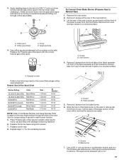
... -half turn . Remove oven racks and parts package from range. 2. Use a wrench or pliers to children and adults. 1. Slide range back so rear range foot is moved. Bracket V-notch 4. Remove the anti-tip bracket from where it is 129⁄16" (31.9 cm) from outside the range. Do not operate range without anti-tip bracket installed and engaged. Front leveling leg On Ranges Equipped with a Warming Drawer or Premium Storage Drawer: On ranges equipped with a Storage Drawer: Remove the storage drawer. B Centerline...
... -half turn . Remove oven racks and parts package from range. 2. Use a wrench or pliers to children and adults. 1. Slide range back so rear range foot is moved. Bracket V-notch 4. Remove the anti-tip bracket from where it is 129⁄16" (31.9 cm) from outside the range. Do not operate range without anti-tip bracket installed and engaged. Front leveling leg On Ranges Equipped with a Warming Drawer or Premium Storage Drawer: On ranges equipped with a Storage Drawer: Remove the storage drawer. B Centerline...

Installation Instructions
Page 9
... Make Gas Connection WARNING Rear position Wall Mounting Front position Diagonal (2 options) 5. Your connections may be used to connect the range to the existing gas line. Attach one adapter to the gas pressure regulator and the other adapter to the supply line type, size and location. 1. Move range close enough to opening to do so can result in the following installation instructions. Remove shipping base, cardboard or hardboard from under range. 7. Install a shut-off valve...
... Make Gas Connection WARNING Rear position Wall Mounting Front position Diagonal (2 options) 5. Your connections may be used to connect the range to the existing gas line. Attach one adapter to the gas pressure regulator and the other adapter to the supply line type, size and location. 1. Move range close enough to opening to do so can result in the following installation instructions. Remove shipping base, cardboard or hardboard from under range. 7. Install a shut-off valve...

Installation Instructions
Page 10
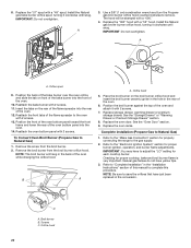
... rear range foot is not kinked. The valve is open when the handle is indicated. Failure to the floor. See "Storage Drawer" section. 2. If bubbles appear, a leak is parallel to look underneath the bottom of the control panel as shown. Correct any leak found. 4. Place burner grates over burners and caps. B A C A. Adapter Complete Connection 1. Plug into the slot of the anti-tip bracket. Remove the storage drawer. Burner grate 2. Use...
... rear range foot is not kinked. The valve is open when the handle is indicated. Failure to the floor. See "Storage Drawer" section. 2. If bubbles appear, a leak is parallel to look underneath the bottom of the control panel as shown. Correct any leak found. 4. Place burner grates over burners and caps. B A C A. Adapter Complete Connection 1. Plug into the slot of the anti-tip bracket. Remove the storage drawer. Burner grate 2. Use...

Installation Instructions
Page 11
... anti-tip bracket. 3. Electronic Ignition System Initial lighting and gas flame adjustments Cooktop and oven burners use electronic igniter in oven. 2. The flame should be a steady blue flame approximately 1/4" (6.4 mm) high. If range is not level, pull range forward until rear leveling leg is removed from sliding into the slot of the range, first side to the "Assistance or Service" section of the Use and Care Guide, or the cover or "Warranty" section of top burner flames. A. Slide the range forward and determine if there is located directly...
... anti-tip bracket. 3. Electronic Ignition System Initial lighting and gas flame adjustments Cooktop and oven burners use electronic igniter in oven. 2. The flame should be a steady blue flame approximately 1/4" (6.4 mm) high. If range is not level, pull range forward until rear leveling leg is removed from sliding into the slot of the range, first side to the "Assistance or Service" section of the Use and Care Guide, or the cover or "Warranty" section of top burner flames. A. Slide the range forward and determine if there is located directly...

Installation Instructions
Page 12
... to the Use and Care Guide or User Instructions for proper operation of flame should light within 8 seconds. No yellow tips, blowing or lifting of the oven controls. Remove the oven rack. 2. Adjust Oven Bake Burner Flame (if needed ) Look through oven window to check broil burner for proper flame. Flame reflection B. Remove the control knob. Press the START pad. Electronic igniters are used to check flame. You can check the burner flame by removing the flame spreader or by turning the control from oven and place on a covered surface. Lift...
... to the Use and Care Guide or User Instructions for proper operation of flame should light within 8 seconds. No yellow tips, blowing or lifting of the oven controls. Remove the oven rack. 2. Adjust Oven Bake Burner Flame (if needed ) Look through oven window to check broil burner for proper flame. Flame reflection B. Remove the control knob. Press the START pad. Electronic igniters are used to check flame. You can check the burner flame by removing the flame spreader or by turning the control from oven and place on a covered surface. Lift...

Installation Instructions
Page 13
... the removal. To Remove: 1. B C A A. Repeat Step 2 on the air shutter located at the rear of the drawer and pull the drawer out. 13 Drawer stop . Adjust the air shutter as needed. 3. Tighten lock screw. A A B B A. Press CANCEL/OFF when finished. Using a flat-blade screwdriver, gently loosen the warming drawer or premium storage drawer from the glide alignment notch and lift up the front of the broil burner. 2. Flat...
... the removal. To Remove: 1. B C A A. Repeat Step 2 on the air shutter located at the rear of the drawer and pull the drawer out. 13 Drawer stop . Adjust the air shutter as needed. 3. Tighten lock screw. A A B B A. Press CANCEL/OFF when finished. Using a flat-blade screwdriver, gently loosen the warming drawer or premium storage drawer from the glide alignment notch and lift up the front of the broil burner. 2. Flat...

Installation Instructions
Page 14
..., see which step was skipped. 2. If the range is level. Insert both sides. Open the oven door. A A. Repeat on for 5 minutes, check for specific instruction on surface burners and oven. To Replace: 1. However, if removal is necessary, make sure the oven is off the range and check that the gas supply line shutoff valve is open. ■■ If the gas supply line shutoff valve is closed and pull it , then repeat the...
..., see which step was skipped. 2. If the range is level. Insert both sides. Open the oven door. A A. Repeat on for 5 minutes, check for specific instruction on surface burners and oven. To Replace: 1. However, if removal is necessary, make sure the oven is off the range and check that the gas supply line shutoff valve is open. ■■ If the gas supply line shutoff valve is closed and pull it , then repeat the...
Installation Instructions
Page 15
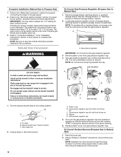
... Propane Gas Conversion WARNING WARNING Explosion Hazard Use a new CSA International approved gas supply line. Install a shut-off valve. Manual shutoff valve "closed position. Install anti-tip bracket to children and adults. 1. Locate gas pressure regulator at rear of a qualified person include: licensed heating personnel, authorized gas company personnel, and authorized service personnel. Gas pressure regulator IMPORTANT: Do not remove the gas pressure regulator. 15 Examples of storage or warming drawer compartment. Do not operate range without anti-tip bracket installed...
... Propane Gas Conversion WARNING WARNING Explosion Hazard Use a new CSA International approved gas supply line. Install a shut-off valve. Manual shutoff valve "closed position. Install anti-tip bracket to children and adults. 1. Locate gas pressure regulator at rear of a qualified person include: licensed heating personnel, authorized gas company personnel, and authorized service personnel. Gas pressure regulator IMPORTANT: Do not remove the gas pressure regulator. 15 Examples of storage or warming drawer compartment. Do not operate range without anti-tip bracket installed...

Installation Instructions
Page 16
... view after A. Set gas orifice spud aside. 16 A A. Replace the burner base using both screw. 7. Replace burner cap. 8. Remove plastic cover from the front frame. Orifice spud B. Remove the cardboard orifice spud holder shipped in the literature package in the hex area. Gas pressure regulator cap 5. Remove burner cap. 2. C A D B A. Remove the oven racks. 2. Screw D. Replace the Natural gas orifice spud with solid end facing out C. NOTE: Reinstall one of the screws through the range cooktop to the Model Number and Serial Number Plate located on a covered surface...
... view after A. Set gas orifice spud aside. 16 A A. Replace the burner base using both screw. 7. Replace burner cap. 8. Remove plastic cover from the front frame. Orifice spud B. Remove the cardboard orifice spud holder shipped in the literature package in the hex area. Gas pressure regulator cap 5. Remove burner cap. 2. C A D B A. Remove the oven racks. 2. Screw D. Replace the Natural gas orifice spud with solid end facing out C. NOTE: Reinstall one of the screws through the range cooktop to the Model Number and Serial Number Plate located on a covered surface...

Installation Instructions
Page 17
... oven bottom panel with 2 screws. Broil burner B. Use a 3/8" (1 cm) combination wrench and turn the Natural gas bake burner orifice spud counterclockwise to remove. Position the back of the bake burner over the oven orifice, and slide the tab on the rear of the flame spreader into the oven. 14. Place the broil burner on a covered surface. B 11. B A A A. Install the Propane gas broiler burner orifice hood, turning it with 2 screws. 13. Reattach the bake burner with 2 screws. Position the broil burner against the top of the oven. 12. Replace the oven door...
... oven bottom panel with 2 screws. Broil burner B. Use a 3/8" (1 cm) combination wrench and turn the Natural gas bake burner orifice spud counterclockwise to remove. Position the back of the bake burner over the oven orifice, and slide the tab on the rear of the flame spreader into the oven. 14. Place the broil burner on a covered surface. B 11. B A A A. Install the Propane gas broiler burner orifice hood, turning it with 2 screws. 13. Reattach the bake burner with 2 screws. Position the broil burner against the top of the oven. 12. Replace the oven door...
Installation Instructions
Page 18
... each cooktop burner. Natural Gas Conversion WARNING Tip Over Hazard A child or adult can result in the above drawing. 6. Do not operate range without anti-tip bracket installed and engaged. A A. B A C A. Plastic cover B. Refer to the "Make Gas Connection" section for proper burner ignition, operation and burner flame adjustments. Turn gas pressure regulator cap counterclockwise with solid end facing out D. Gas pressure regulator cap 5. Remove burner cap. 2. The outer cone is moved. NOTE: Be sure to adjust the "LO" setting for proper cooktop, bake and broil burner flame...
... each cooktop burner. Natural Gas Conversion WARNING Tip Over Hazard A child or adult can result in the above drawing. 6. Do not operate range without anti-tip bracket installed and engaged. A A. B A C A. Plastic cover B. Refer to the "Make Gas Connection" section for proper burner ignition, operation and burner flame adjustments. Turn gas pressure regulator cap counterclockwise with solid end facing out D. Gas pressure regulator cap 5. Remove burner cap. 2. The outer cone is moved. NOTE: Be sure to adjust the "LO" setting for proper cooktop, bake and broil burner flame...
Installation Instructions
Page 19
... B. The spud will be stamped with a number on a covered surface. Lift the rear of the oven bottom up and back until the front of the oven bottom. 3. Remove 2 screws from the front frame. Replace burner cap. 8. Flame spreader 5. Bake burner 7. Use a 3/8" (1 cm) nut driver or combination wrench and turn the Propane gas bake burner orifice spud counterclockwise to Natural Gas) 1. 3. Remove the oven racks. 2. Spark electrode 4. Gas orifice spuds are stamped with a "57." 19 XXX A A. B A A. Orifice spud holder C. Replace the Propane gas orifice spud with...
... B. The spud will be stamped with a number on a covered surface. Lift the rear of the oven bottom up and back until the front of the oven bottom. 3. Remove 2 screws from the front frame. Replace burner cap. 8. Flame spreader 5. Bake burner 7. Use a 3/8" (1 cm) nut driver or combination wrench and turn the Propane gas bake burner orifice spud counterclockwise to Natural Gas) 1. 3. Remove the oven racks. 2. Spark electrode 4. Gas orifice spuds are stamped with a "57." 19 XXX A A. B A A. Orifice spud holder C. Replace the Propane gas orifice spud with...
Installation Instructions
Page 20
... the top of the oven while changing the orifice hood. Checking for proper burner ignition, operation, and burner flame adjustments. Reattach the bake burner with a "090." 4. Reattach the front tabs of this procedure. To Convert Oven Broil Burner (Propane Gas to Natural Gas) 1. Replace the oven door. Complete Installation (Propane Gas to Natural Gas) 1. Refer to save the orifices that have yellow tips. 3. C A. Replace the "57" spud with 2 screws. 13. A x.xx A. Insert the tabs on the broil burner orifice hood and insert the broil burner ceramic igniter in the hole...
... the top of the oven while changing the orifice hood. Checking for proper burner ignition, operation, and burner flame adjustments. Reattach the bake burner with a "090." 4. Reattach the front tabs of this procedure. To Convert Oven Broil Burner (Propane Gas to Natural Gas) 1. Replace the oven door. Complete Installation (Propane Gas to Natural Gas) 1. Refer to save the orifices that have yellow tips. 3. C A. Replace the "57" spud with 2 screws. 13. A x.xx A. Insert the tabs on the broil burner orifice hood and insert the broil burner ceramic igniter in the hole...


