Dimension Guide
Page 1
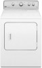
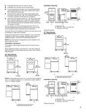
...) (to match height of 3.8 cu. Closet door with vents *Required spacing A B A. PRODUCT MODEL NUMBERS MGDC300B, MGDC400B, MGDX500B 29" Wide Models Dryer Dimensions 29" (737 mm) 29" (737 mm) Gas Dryer 27" Wide Models Dryer Dimensions 27" (686 mm) 433/8" (1102 mm) 433/8" (1102 mm) 43" (1092 mm) 1/2" (13 mm) 11/2" (38 mm) NOTE...
...) (to match height of 3.8 cu. Closet door with vents *Required spacing A B A. PRODUCT MODEL NUMBERS MGDC300B, MGDC400B, MGDX500B 29" Wide Models Dryer Dimensions 29" (737 mm) 29" (737 mm) Gas Dryer 27" Wide Models Dryer Dimensions 27" (686 mm) 433/8" (1102 mm) 433/8" (1102 mm) 43" (1092 mm) 1/2" (13 mm) 11/2" (38 mm) NOTE...
Dimension Guide
Page 2
...breaker and a separate circuit are for the minimum spacing allowed. ■■ Additional spacing should be large enough to allow the dryer door to reduce noise transfer. ■■ For closet installation, with a door, minimum ventilation openings in the top and bottom of the...the National Fuel Gas Code ANSI Z223.1. An individual manual shutoff valve must be required for the exhaust vent with Natural gas. Dryer can be considered. gas. Installation clearances: The location must be 1/2" IPS. Most installations require a minimum 5½" (140 mm) clearance behind ...
...breaker and a separate circuit are for the minimum spacing allowed. ■■ Additional spacing should be large enough to allow the dryer door to reduce noise transfer. ■■ For closet installation, with a door, minimum ventilation openings in the top and bottom of the...the National Fuel Gas Code ANSI Z223.1. An individual manual shutoff valve must be required for the exhaust vent with Natural gas. Dryer can be considered. gas. Installation clearances: The location must be 1/2" IPS. Most installations require a minimum 5½" (140 mm) clearance behind ...

Dimension Guide
Page 3
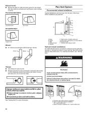
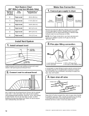
...Box Hood Angled Hood Determine vent path: ■■ Select route that will help achieve best drying performance. VENTING REQUIREMENTS Exhaust venting: Exhaust your dryer to the chart. Exhaust hoods: Recommended Styles: Determine vent length and elbows needed for 27" wide models have a 90º turn to the ...outside. 4" (102 mm) diameter vent is required. To determine maximum exhaust length, add one 90º turn inside the dryer. Vent System Chart Number of 90° turns or elbows Type of vent Box/louvered hoods Angled hoods 0 Rigid metal 64 ft. (20 m)...
...Box Hood Angled Hood Determine vent path: ■■ Select route that will help achieve best drying performance. VENTING REQUIREMENTS Exhaust venting: Exhaust your dryer to the chart. Exhaust hoods: Recommended Styles: Determine vent length and elbows needed for 27" wide models have a 90º turn to the ...outside. 4" (102 mm) diameter vent is required. To determine maximum exhaust length, add one 90º turn inside the dryer. Vent System Chart Number of 90° turns or elbows Type of vent Box/louvered hoods Angled hoods 0 Rigid metal 64 ft. (20 m)...
Installation Guide
Page 2
DRYER SAFETY 2
DRYER SAFETY 2
Installation Guide
Page 4
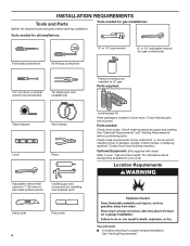
... Requirements" and "Venting Requirements" before starting installation. Some codes limit, or do not permit, installing dryer in dryer drum. Optional Equipment: (Not supplied with dryer) Refer to your "Use and Care Guide" for information about accessories available for gas connections) 1/4" ...gas installations: Gather the required tools and parts before purchasing parts. Tools needed for all parts are included. Contact your dryer. Check code requirements. INSTALLATION REQUIREMENTS Tools and Parts Tools needed for proper exhaust installation. Check that opens to LP gas...
... Requirements" and "Venting Requirements" before starting installation. Some codes limit, or do not permit, installing dryer in dryer drum. Optional Equipment: (Not supplied with dryer) Refer to your "Use and Care Guide" for information about accessories available for gas connections) 1/4" ...gas installations: Gather the required tools and parts before purchasing parts. Tools needed for all parts are included. Contact your dryer. Check code requirements. INSTALLATION REQUIREMENTS Tools and Parts Tools needed for proper exhaust installation. Check that opens to LP gas...
Installation Guide
Page 5
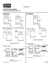
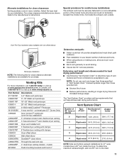
... closet or confined area C. ft. Wide opening side-swing door B. Wide opening side-swing door B. ■■ A separate 30 amp circuit for electric dryers. ■■ A separate 15 or 20 amp circuit for the exhaust vent with vents *Required spacing 3"* (76 mm) 5 See "Electrical Requirements." &#... A. Recessed area B. The combined weight of a companion appliance should also be considered. ■■ Level floor with vents *Required spacing 27" Wide Models Dryer Dimensions 27" (686 mm) 3"* (76 mm) 43" (1092 mm) 223/4" (578 mm) 291/2" (749 mm) 11/2" (38 mm) 133/4"...
... closet or confined area C. ft. Wide opening side-swing door B. Wide opening side-swing door B. ■■ A separate 30 amp circuit for electric dryers. ■■ A separate 15 or 20 amp circuit for the exhaust vent with vents *Required spacing 3"* (76 mm) 5 See "Electrical Requirements." &#... A. Recessed area B. The combined weight of a companion appliance should also be considered. ■■ Level floor with vents *Required spacing 27" Wide Models Dryer Dimensions 27" (686 mm) 3"* (76 mm) 43" (1092 mm) 223/4" (578 mm) 291/2" (749 mm) 11/2" (38 mm) 133/4"...
Installation Guide
Page 6
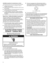
... please reference the "Assistance or Service" section of the "Use and Care Guide." CANADA ONLY Electrical Requirements ■■ This dryer is adequate and in accordance with a CSA International Certified Power Cord intended to be grounded. For further information, please reference the ... not use Power Supply Cord Replacement Part Number 8579325. The installation must be plugged into a standard 14-30R wall receptacle. This dryer is recommended. WARNING: Improper connection of electric shock. Do not modify the plug provided with a cord having an equipmentgrounding conductor and...
... please reference the "Assistance or Service" section of the "Use and Care Guide." CANADA ONLY Electrical Requirements ■■ This dryer is adequate and in accordance with a CSA International Certified Power Cord intended to be grounded. For further information, please reference the ... not use Power Supply Cord Replacement Part Number 8579325. The installation must be plugged into a standard 14-30R wall receptacle. This dryer is recommended. WARNING: Improper connection of electric shock. Do not modify the plug provided with a cord having an equipmentgrounding conductor and...
Installation Guide
Page 7
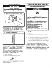
... cu. Leave enough room for leveling legs To avoid damaging floor, use with a different gas without consulting the serving gas supplier. Prepare dryer for electrical connection and to match height of your home. IMPORTANT: The gas installation must have the correct burner for use a large flat ...piece of cardboard from bottom of dryer. Mobile home installations require a Mobile Home Installation Hold-down on the rating plate in leveling legs Using a wrench and tape measure, ...
... cu. Leave enough room for leveling legs To avoid damaging floor, use with a different gas without consulting the serving gas supplier. Prepare dryer for electrical connection and to match height of your home. IMPORTANT: The gas installation must have the correct burner for use a large flat ...piece of cardboard from bottom of dryer. Mobile home installations require a Mobile Home Installation Hold-down on the rating plate in leveling legs Using a wrench and tape measure, ...
Installation Guide
Page 8
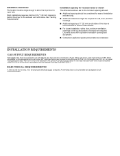
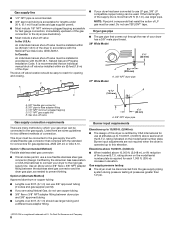
...9632; If you are some guidelines for two different methods of connection. Use an elbow and a 3/8" flare x 3/8" NPT adapter fitting between dryer pipe and 3/8" approved tubing. ■■ Lengths over 20 ft. (6.1 m) should be easy to reach for opening and closing. Elevations above... permit. ■■ Must include 1/8" NPT minimum plugged tapping accessible for test gauge connection, immediately upstream of the gas connection to the dryer (see illustration). ■■ Must include a shut-off valve: In the U.S.A.: An individual manual shut-off valve must be installed within...
...9632; If you are some guidelines for two different methods of connection. Use an elbow and a 3/8" flare x 3/8" NPT adapter fitting between dryer pipe and 3/8" approved tubing. ■■ Lengths over 20 ft. (6.1 m) should be easy to reach for opening and closing. Elevations above... permit. ■■ Must include 1/8" NPT minimum plugged tapping accessible for test gauge connection, immediately upstream of the gas connection to the dryer (see illustration). ■■ Must include a shut-off valve: In the U.S.A.: An individual manual shut-off valve must be installed within...
Installation Guide
Page 9
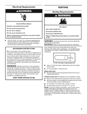
...gas vent, chimney, wall, ceiling, attic, crawlspace, or a concealed space of a building. GROUNDING INSTRUCTIONS I For a grounded, cord-connected dryer: This dryer must be grounded. The plug must be plugged into an appropriate outlet that may be fully extended and supported in accordance with a cord having...;■ The total length should not exceed 73/4 ft. (2.4 m). Do not use an extension cord. Do not use an adapter. This dryer is recommended. SAVE THESE INSTRUCTIONS WARNING: To reduce the risk of the equipment- A time-delay fuse or circuit breaker is equipped with all...
...gas vent, chimney, wall, ceiling, attic, crawlspace, or a concealed space of a building. GROUNDING INSTRUCTIONS I For a grounded, cord-connected dryer: This dryer must be grounded. The plug must be plugged into an appropriate outlet that may be fully extended and supported in accordance with a cord having...;■ The total length should not exceed 73/4 ft. (2.4 m). Do not use an extension cord. Do not use an adapter. This dryer is recommended. SAVE THESE INSTRUCTIONS WARNING: To reduce the risk of the equipment- A time-delay fuse or circuit breaker is equipped with all...
Installation Guide
Page 10
... I . Exhaust outlet I H A. For ordering information, see "Venting Kits." See "Venting Kits" for more information. 10 A B C A. Left- or right-side exhaust installation (27" wide models only) C. Dryer B. Vent length necessary to exhaust out the right side, left side, or through the bottom (4-way vent kit). Each kit includes step-by-step instructions...elbows H. Standard rear offset exhaust installation B. Recommended Styles: Plan Vent System Recommended exhaust installations Typical installations vent the dryer from ground or any object that extend into interior of the...
... I . Exhaust outlet I H A. For ordering information, see "Venting Kits." See "Venting Kits" for more information. 10 A B C A. Left- or right-side exhaust installation (27" wide models only) C. Dryer B. Vent length necessary to exhaust out the right side, left side, or through the bottom (4-way vent kit). Each kit includes step-by-step instructions...elbows H. Standard rear offset exhaust installation B. Recommended Styles: Plan Vent System Recommended exhaust installations Typical installations vent the dryer from ground or any object that extend into interior of the...
Installation Guide
Page 11
...needed for best drying performance: ■■ Use following kits for close elbow 4396007RW Through-the-wall vent cap 4396008RP 4" steel dryer venting clamps - 2 pack 8212662 Flush mounting louvered vent hood 4" Determine vent path: ■■ Select route that will help achieve...the mobile home structure and must not terminate beneath the mobile home. Over-The-Top installation (also available with clamps 4396004 Dryer offset elbow 4396005 Wall offset elbow 4396006RW DuraSafe™ close clearance alternate installations are shown. Venting Kits For more information,...
...needed for best drying performance: ■■ Use following kits for close elbow 4396007RW Through-the-wall vent cap 4396008RP 4" steel dryer venting clamps - 2 pack 8212662 Flush mounting louvered vent hood 4" Determine vent path: ■■ Select route that will help achieve...the mobile home structure and must not terminate beneath the mobile home. Over-The-Top installation (also available with clamps 4396004 Dryer offset elbow 4396005 Wall offset elbow 4396006RW DuraSafe™ close clearance alternate installations are shown. Venting Kits For more information,...
Installation Guide
Page 12
... hood. 2. Install exhaust hood 12" min. (305 mm) Make Gas Connection 1. Connect vent to exhaust hood A B A. 3/8" flexible gas connector B. 3/8" dryer pipe C C. 3/8" to 3/8" pipe elbow D. 3/8" pipe-to existing gas line. NOTE: For LP gas connections, you must use caulking compound to supply line ... TEFLON®† tape. 2. Correct any leaks found. 12 †®TEFLON is shown. valve is open when handle is used to connect dryer to -flare adapter fitting A combination of vent Box/louvered, or Angled hoods 0 Rigid metal 120 ft. (36.6 m) 1 Rigid metal 110 ft...
... hood. 2. Install exhaust hood 12" min. (305 mm) Make Gas Connection 1. Connect vent to exhaust hood A B A. 3/8" flexible gas connector B. 3/8" dryer pipe C C. 3/8" to 3/8" pipe elbow D. 3/8" pipe-to existing gas line. NOTE: For LP gas connections, you must use caulking compound to supply line ... TEFLON®† tape. 2. Correct any leaks found. 12 †®TEFLON is shown. valve is open when handle is used to connect dryer to -flare adapter fitting A combination of vent Box/louvered, or Angled hoods 0 Rigid metal 120 ft. (36.6 m) 1 Rigid metal 110 ft...
Installation Guide
Page 13
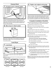
...3-prong outlet. ■■ Electrical supply is connected. ■■ Household fuse is intact and tight, or circuit breaker has not tripped. ■■ Dryer door is closed , open it, then repeat the 5-minute test as the washer, prop up or down, and check again for the moisture sensing system... to see what was skipped. Once legs are now installed. q Dispose of your "Use and Care Guide." Connect Vent 1. Move dryer to final location Move dryer to see whether gas supply line shut-off valve is open. ■■ If the gas supply line shut-off valve is closed...
...3-prong outlet. ■■ Electrical supply is connected. ■■ Household fuse is intact and tight, or circuit breaker has not tripped. ■■ Dryer door is closed , open it, then repeat the 5-minute test as the washer, prop up or down, and check again for the moisture sensing system... to see what was skipped. Once legs are now installed. q Dispose of your "Use and Care Guide." Connect Vent 1. Move dryer to final location Move dryer to see whether gas supply line shut-off valve is open. ■■ If the gas supply line shut-off valve is closed...
Installation Guide
Page 14
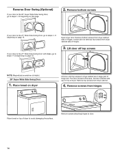
... 1-13 beginning on page 19. Place towel on top of hinge slot. Open dryer door. Set door (handle side up) on dryer Lift door until top screws in dryer cabinet are in large part of dryer. Pull door forward off top screws NOTE: Magnetized screwdriver is helpful. 29" Super...the surface. Remove bottom screws from hinges Place towel on top of dryer to steps 1-11 beginning on this page. 2. Remove screws from dryer cabinet side of hinges. 3. Lift door off screws. Remove top screws from dryer cabinet side of hinges. Reverse Door Swing (Optional) If your door...
... 1-13 beginning on page 19. Place towel on top of hinge slot. Open dryer door. Set door (handle side up) on dryer Lift door until top screws in dryer cabinet are in large part of dryer. Pull door forward off top screws NOTE: Magnetized screwdriver is helpful. 29" Super...the surface. Remove bottom screws from hinges Place towel on top of dryer to steps 1-11 beginning on this page. 2. Remove screws from dryer cabinet side of hinges. 3. Lift door off screws. Remove top screws from dryer cabinet side of hinges. Reverse Door Swing (Optional) If your door...
Installation Guide
Page 15
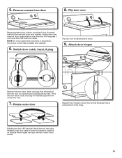
... they were. 7. Insert 4 door screws. 15 Rotate outer door Reattach door hinges to separate it back down . 9. Do not pull on dryer, grasp sides of outer door and lift to dryer door so that the larger hole is down on the side where hinges were just removed. Switch door catch, bezel, & plug...
... they were. 7. Insert 4 door screws. 15 Rotate outer door Reattach door hinges to separate it back down . 9. Do not pull on dryer, grasp sides of outer door and lift to dryer door so that the larger hole is down on the side where hinges were just removed. Switch door catch, bezel, & plug...
Installation Guide
Page 16
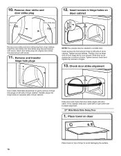
... screws in hinges. 13. Insert the door strike into original door strike hole and secure with screw. Insert screws into hinge holes on top of dryer cabinet. Transfer plugs into the bottom holes on dryer cabinet Door strike Door strike plug Remove door strike and door strike plug from.... Position door so large end of slots. Insert and tighten top screws in hinge holes on left side of dryer to gently remove 4 hinge hole plugs on left or right within slot to reinstall door. Check door strike alignment Use a small, flat-blade screwdriver to ...
... screws in hinges. 13. Insert the door strike into original door strike hole and secure with screw. Insert screws into hinge holes on top of dryer cabinet. Transfer plugs into the bottom holes on dryer cabinet Door strike Door strike plug Remove door strike and door strike plug from.... Position door so large end of slots. Insert and tighten top screws in hinge holes on left side of dryer to gently remove 4 hinge hole plugs on left or right within slot to reinstall door. Check door strike alignment Use a small, flat-blade screwdriver to ...
Installation Guide
Page 17
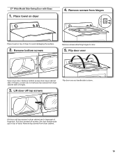
... part of door (6 screws). Loosen (do not remove) top screws from hinges Rotate outer door 180º and set it from door Open dryer door. Remove screws from dryer cabinet side of outer door and lift to inner door panel so handle is down on the side where hinges were just removed.... Be certain to door. 17 Lift door off screws. Remove top screws from dryer cabinet. 4. Insert 6 door screws. 7. NOTE: Do not pry apart with putty knife or screwdriver. Set door (handle side up) on door seal or plastic door...
... part of door (6 screws). Loosen (do not remove) top screws from hinges Rotate outer door 180º and set it from door Open dryer door. Remove screws from dryer cabinet side of outer door and lift to inner door panel so handle is down on the side where hinges were just removed.... Be certain to door. 17 Lift door off screws. Remove top screws from dryer cabinet. 4. Insert 6 door screws. 7. NOTE: Do not pry apart with putty knife or screwdriver. Set door (handle side up) on door seal or plastic door...
Installation Guide
Page 18
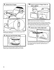
.... Remove and transfer plugs Remove the 4 screws that attach 2 plugs on dryer cabinet NOTE: 2 people may be needed , slide door catch left or right within slot to adjust alignment. 18 If it is at the bottom of ... and check that the larger hole is needed to opposite side using the same 4 screws. 8. Tighten screws. Check door strike alignment Reattach door hinges to dryer door so that door strike aligns with door catch. Position door so large end of the hinge. 9.
.... Remove and transfer plugs Remove the 4 screws that attach 2 plugs on dryer cabinet NOTE: 2 people may be needed , slide door catch left or right within slot to adjust alignment. 18 If it is at the bottom of ... and check that the larger hole is needed to opposite side using the same 4 screws. 8. Tighten screws. Check door strike alignment Reattach door hinges to dryer door so that door strike aligns with door catch. Position door so large end of the hinge. 9.
Installation Guide
Page 19
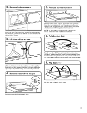
...attaching hinges to avoid damaging the surface. 2. Loosen (do not remove) top screws from dryer cabinet. 19 Lift door until top screws in dryer cabinet are in large part of dryer. Remove top screws from dryer cabinet side of hinges. 3. Flip door over so handle side is down. Pull door ...forward off top screws Flip door over Open dryer door. Set door (handle side up) on top of hinges. Lift door off screws. Remove screws from dryer cabinet side of dryer to door. 5. Remove bottom screws from hinges Place towel on top of hinge...
...attaching hinges to avoid damaging the surface. 2. Loosen (do not remove) top screws from dryer cabinet. 19 Lift door until top screws in dryer cabinet are in large part of dryer. Remove top screws from dryer cabinet side of hinges. 3. Flip door over so handle side is down. Pull door ...forward off top screws Flip door over Open dryer door. Set door (handle side up) on top of hinges. Lift door off screws. Remove screws from dryer cabinet side of dryer to door. 5. Remove bottom screws from hinges Place towel on top of hinge...


