
W10240504
Page 7
...times. 4 L1 voltage check completes. If electric (Fuel = Electric): The UI will report findings per the "Gas Dryer Results Display" section where Heater Voltage is available and Airflow is not available. Check for POWER) are published to display... as in Step 4. If gas (Fuel = Gas): The UI will report findings per the "Electric Dryer Results Display" section where L2 Voltage is available, L1 Voltage is not ...
...times. 4 L1 voltage check completes. If electric (Fuel = Electric): The UI will report findings per the "Gas Dryer Results Display" section where Heater Voltage is available and Airflow is not available. Check for POWER) are published to display... as in Step 4. If gas (Fuel = Gas): The UI will report findings per the "Electric Dryer Results Display" section where L2 Voltage is available, L1 Voltage is not ...
W10240504
Page 8
...Frame 5: Htr Frame 6: When the voltage is not yet available to the UI, the display will report findings per the "Gas Dryer Results Display" section where Heater Voltage is available and Airflow is present, it is available. When the voltage or airflow is ... Frame 3: L1 Frame 4: When the voltage is not yet available to 200). Frame 7: Air Frame 8: See "Airflow Display Section". Gas Dryer Results Display The frame rate will be 0.5 seconds per frame. The text will show "---". When the voltage or airflow is available to ...
...Frame 5: Htr Frame 6: When the voltage is not yet available to the UI, the display will report findings per the "Gas Dryer Results Display" section where Heater Voltage is available and Airflow is present, it is available. When the voltage or airflow is ... Frame 3: L1 Frame 4: When the voltage is not yet available to 200). Frame 7: Air Frame 8: See "Airflow Display Section". Gas Dryer Results Display The frame rate will be 0.5 seconds per frame. The text will show "---". When the voltage or airflow is available to ...
W10240504
Page 10
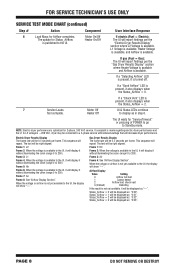
...that the exhaust thermistor is not plugged into the power outlet. • Unplug dryer or disconnect power and check the relay connections on the ACU. • Gas Models Only: Unplug dryer or disconnect power and check the P14 connection on the ACU (harness loopback on ...and UI. • Check AC and DC supplies. F2E1 User Interface (UI) Stuck Button Indicates a stuck button (depressed for the dryer model displaying the fault/error code. F6E3 Communication Error: • Check the harness continuity and connections between the ACU and UI has...
...that the exhaust thermistor is not plugged into the power outlet. • Unplug dryer or disconnect power and check the relay connections on the ACU. • Gas Models Only: Unplug dryer or disconnect power and check the P14 connection on the ACU (harness loopback on ...and UI. • Check AC and DC supplies. F2E1 User Interface (UI) Stuck Button Indicates a stuck button (depressed for the dryer model displaying the fault/error code. F6E3 Communication Error: • Check the harness continuity and connections between the ACU and UI has...

W10240504
Page 12
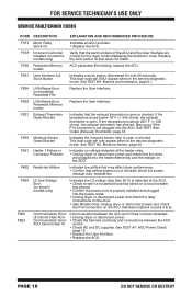
... power. If +5VDC is present, go to step 7. 7. Unplug dryer or disconnect power. Failure to use of needle probes to step 6. 6. This test assumes that proper voltage is present at the outlet: 240VAC (electric 2-phase), 208VAC (electric 3-phase), or 120VAC (gas). If line voltage is present, go to measure voltage...
... power. If +5VDC is present, go to step 7. 7. Unplug dryer or disconnect power. Failure to use of needle probes to step 6. 6. This test assumes that proper voltage is present at the outlet: 240VAC (electric 2-phase), 208VAC (electric 3-phase), or 120VAC (gas). If line voltage is present, go to measure voltage...
W10240504
Page 13
... Visually check that ALL connectors are secure, replace the main wire harness. 8. Reassemble all parts and panels. 10. ELECTRIC DRYER (Canadian Installations): 1. Access the machine electronics without disconnecting any wiring to step 4. 4. Reassemble all parts and panels. 11.... indicates that wires to the terminal block (electric dryer) or wire harness connection (gas dryer). Cover Plate Remove Screws Figure 3 - Check for electric dryer. 5. Remove the cover plate from the top right corner of the back of the dryer. If acceptable, replace the UI. 8. Installations):...
... Visually check that ALL connectors are secure, replace the main wire harness. 8. Reassemble all parts and panels. 10. ELECTRIC DRYER (Canadian Installations): 1. Access the machine electronics without disconnecting any wiring to step 4. 4. Reassemble all parts and panels. 11.... indicates that wires to the terminal block (electric dryer) or wire harness connection (gas dryer). Cover Plate Remove Screws Figure 3 - Check for electric dryer. 5. Remove the cover plate from the top right corner of the back of the dryer. If acceptable, replace the UI. 8. Installations):...
W10240504
Page 14
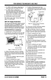
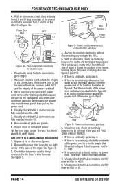
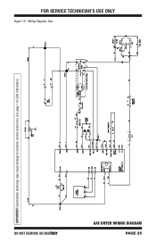
...power cord's L1 wire. If an open circuit is necessary to the harness in figure 5. In a similar way, check for gas dryer. harness to -wire harness connection for continuity between the neutral (N) terminal of the power cord to replace the power cord, remove the ...the power cord plug. Reassemble all parts and panels. 9. Access the machine electronics without disconnecting any wiring to verify repair. Power cord terminals, gas dryer. 6. Power Cord Plug N Neu L1 ACU P9 L1 1 Wire Harness Power Cord Figure 5 - and the integrity of the power cord neutral...
...power cord's L1 wire. If an open circuit is necessary to the harness in figure 5. In a similar way, check for gas dryer. harness to -wire harness connection for continuity between the neutral (N) terminal of the power cord to replace the power cord, remove the ...the power cord plug. Reassemble all parts and panels. 9. Access the machine electronics without disconnecting any wiring to verify repair. Power cord terminals, gas dryer. 6. Power Cord Plug N Neu L1 ACU P9 L1 1 Wire Harness Power Cord Figure 5 - and the integrity of the power cord neutral...
W10240504
Page 15
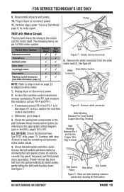
...System Harness/connection Thermal fuse Belt/belt switch Drive motor Centrifugal switch Door switch Machine control electronics (See ESD information, page 1) Electric Dryer ü ü Gas Dryer ü ü Drum Belt Figure 7 - Remove white connector. DO NOT REMOVE OR DESTROY PAGE 15 The following items are...", page 6, to remove console, top panel, toe panel, and front panel/ drum assembly). Slowly remove drum belt. 5. Unplug dryer or disconnect power. 2. Plug in the path between these measurement points by removing the back panel screws (to verify repair. ALL...
...System Harness/connection Thermal fuse Belt/belt switch Drive motor Centrifugal switch Door switch Machine control electronics (See ESD information, page 1) Electric Dryer ü ü Gas Dryer ü ü Drum Belt Figure 7 - Remove white connector. DO NOT REMOVE OR DESTROY PAGE 15 The following items are...", page 6, to remove console, top panel, toe panel, and front panel/ drum assembly). Slowly remove drum belt. 5. Unplug dryer or disconnect power. 2. Plug in the path between these measurement points by removing the back panel screws (to verify repair. ALL...
W10240504
Page 16
...-off This test checks the components making up the belt switch pulley. If the resistance reading goes from infinity to the dryer. If not, replace the belt switch. If belt switch is OK and there is still an open circuit between pin ... not heat 3 Heat will not shut off High limit thermostat Heat element assembly Gas valve assembly Centrifugal switch Outlet thermistor Machine control electronics Console electronics and housing assembly Gas supply Electric Dryer no ü ü ü ü Gas Dryer ü ü ü ü no ü ü ü ü ü...
...-off This test checks the components making up the belt switch pulley. If the resistance reading goes from infinity to the dryer. If not, replace the belt switch. If belt switch is OK and there is still an open circuit between pin ... not heat 3 Heat will not shut off High limit thermostat Heat element assembly Gas valve assembly Centrifugal switch Outlet thermistor Machine control electronics Console electronics and housing assembly Gas supply Electric Dryer no ü ü ü ü Gas Dryer ü ü ü ü no ü ü ü ü ü...
W10240504
Page 17
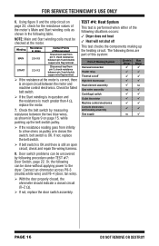
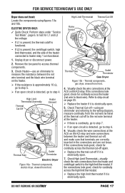
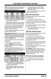
...). High Limit Thermostat Assembly Thermal Cut-Off Heater Element Thermal Fuse Outlet Thermistor Electric Dryer Figure 10a - High Limit Thermostat Thermal Cut-Off Flame Sensor Thermal Fuse Outlet Thermistor Gas Dryer Figure 10b - Visually check the wire connections at the ACU on the K2 relay...-use an ohmmeter to measure the resistance between the heater and thermal cut -off -using figures 10a and 10b. Thermal components, electric dryer, viewed from front. 4. If the connections look good, check for continuity across the high limit thermostat. Replace the high ...
...). High Limit Thermostat Assembly Thermal Cut-Off Heater Element Thermal Fuse Outlet Thermistor Electric Dryer Figure 10a - High Limit Thermostat Thermal Cut-Off Flame Sensor Thermal Fuse Outlet Thermistor Gas Dryer Figure 10b - Visually check the wire connections at the ACU on the K2 relay...-use an ohmmeter to measure the resistance between the heater and thermal cut -off -using figures 10a and 10b. Thermal components, electric dryer, viewed from front. 4. If the connections look good, check for continuity across the high limit thermostat. Replace the high ...
W10240504
Page 18
...maintain the desired temperature. If the preceding steps did not correct the problem, suspect the centrifugal switch before replacing the ACU. 10. GAS DRYER ONLY: 1. Plug in dryer or reconnect power. 10. Measure the voltage across terminals 1 & 2 for the K2 heater relay. If voltage is ...1 & 2 of the K2 relay at the connector. With a voltmeter set to AC, connect voltmeter to step 8. 7. Plug in dryer or reconnect power. Verify the gas supply to strip circuit on . 2. Locate the high limit thermostat (see figure 10b, page 17). Reassemble all parts and panels. 11...
...maintain the desired temperature. If the preceding steps did not correct the problem, suspect the centrifugal switch before replacing the ACU. 10. GAS DRYER ONLY: 1. Plug in dryer or reconnect power. 10. Measure the voltage across terminals 1 & 2 for the K2 heater relay. If voltage is ...1 & 2 of the K2 relay at the connector. With a voltmeter set to AC, connect voltmeter to step 8. 7. Plug in dryer or reconnect power. Verify the gas supply to strip circuit on . 2. Locate the high limit thermostat (see figure 10b, page 17). Reassemble all parts and panels. 11...
W10240504
Page 19
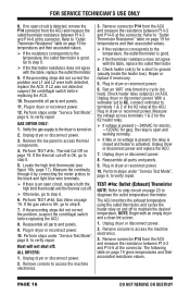
... by removing the toe panel. In addition, check for blocked or improper exhaust system, and, on electric dryers, for location. 4. Access the thermal fuse by removing the toe panel. Access the gas valve by removing the toe panel. OUTLET THERMISTOR RESISTANCE TEMP. °F (°C) 50° (10&#... If the preceding steps did not correct the problem, replace the ACU. otherwise, proceed to ground (short), replace wiring harness; TEST #4d: Gas Valve (Gas Dryer) 1. Temperature Levels Incorrect - If either pin indicates continuity to step 5. 5. Remove load from ACU.
... by removing the toe panel. In addition, check for blocked or improper exhaust system, and, on electric dryers, for location. 4. Access the thermal fuse by removing the toe panel. Access the gas valve by removing the toe panel. OUTLET THERMISTOR RESISTANCE TEMP. °F (°C) 50° (10&#... If the preceding steps did not correct the problem, replace the ACU. otherwise, proceed to ground (short), replace wiring harness; TEST #4d: Gas Valve (Gas Dryer) 1. Temperature Levels Incorrect - If either pin indicates continuity to step 5. 5. Remove load from ACU.
W10240504
Page 20
... If there is continuity, reconnect the sensor wires and continue to step 5. 5. Measuring gas valve resistance. 4. NOTE: Dryer will shut down automatically after 2½ hours. Plug in dryer or reconnect power. 13. Part of this system: Black Light Blue White White Light Blue Figure...61656; If there is open , replace the ignitor. If resistance readings are part of Moisture System Harness/connection Electric Gas Dryer Dryer Metal sensor strips Machine control electronics NOTE: Refer to strip circuit on , line voltage may not be caused by removing the toe...
... If there is continuity, reconnect the sensor wires and continue to step 5. 5. Measuring gas valve resistance. 4. NOTE: Dryer will shut down automatically after 2½ hours. Plug in dryer or reconnect power. 13. Part of this system: Black Light Blue White White Light Blue Figure...61656; If there is open , replace the ignitor. If resistance readings are part of Moisture System Harness/connection Electric Gas Dryer Dryer Metal sensor strips Machine control electronics NOTE: Refer to strip circuit on , line voltage may not be caused by removing the toe...
W10240504
Page 25
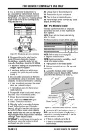
FOR SERVICE TECHNICIAN'S USE ONLY Figure 15 - See page 1 for ESD information. Wiring Diagram, Gas IMPORTANT: Electrostatic discharge may cause damage to machine control electronics. DO NOT REMOVE OR DESTROY GAS DRYER WIRING DIAGRAM PAGE 25
FOR SERVICE TECHNICIAN'S USE ONLY Figure 15 - See page 1 for ESD information. Wiring Diagram, Gas IMPORTANT: Electrostatic discharge may cause damage to machine control electronics. DO NOT REMOVE OR DESTROY GAS DRYER WIRING DIAGRAM PAGE 25
W10240504
Page 26
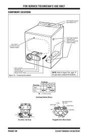
... OR DESTROY Component locations. Contacts Function 1M 2M 3M 5M 6M Start Run = Contacts closed Centrifugal Switch (Motor) Black Light Blue White White Light Blue Gas Valve, Gas Dryer Lt. FOR SERVICE TECHNICIAN'S USE ONLY COMPONENT LOCATIONS • ACU (beneath console) • User Interface (UI) Door Switch (Location may vary between models) •...; Heater Assembly • Motor Assembly • Thermal Fuse • Outlet Thermistor • Moisture Sensor Strips Figure 16 - NOTE: Refer to Figure 10b, page 17, for gas dryer component locations.
... OR DESTROY Component locations. Contacts Function 1M 2M 3M 5M 6M Start Run = Contacts closed Centrifugal Switch (Motor) Black Light Blue White White Light Blue Gas Valve, Gas Dryer Lt. FOR SERVICE TECHNICIAN'S USE ONLY COMPONENT LOCATIONS • ACU (beneath console) • User Interface (UI) Door Switch (Location may vary between models) •...; Heater Assembly • Motor Assembly • Thermal Fuse • Outlet Thermistor • Moisture Sensor Strips Figure 16 - NOTE: Refer to Figure 10b, page 17, for gas dryer component locations.

