
Installation Guide
Page 1
U.S.A. Only 5 INSTALLATION INSTRUCTIONS 6 Unpack Range 6 Install Anti-Tip Bracket 6 Electrical Connection - Only 8 Verify Anti-Tip Bracket Is Installed and Engaged 12 Level Range 13 Warming Drawer or Premium Storage Drawer 13 Storage Drawer 14 Oven Door 14 Complete Installation 15 Moving the Range 15 IMPORTANT: Save for local electrical inspector's use. U.S.A. INSTALLATION INSTRUCTIONS 30" (76 CM) FREESTANDING ELECTRIC RANGES Table of Contents RANGE SAFETY 2 INSTALLATION REQUIREMENTS 3 Tools and Parts 3 Location Requirements 3 Electrical Requirements - W10403811B
U.S.A. Only 5 INSTALLATION INSTRUCTIONS 6 Unpack Range 6 Install Anti-Tip Bracket 6 Electrical Connection - Only 8 Verify Anti-Tip Bracket Is Installed and Engaged 12 Level Range 13 Warming Drawer or Premium Storage Drawer 13 Storage Drawer 14 Oven Door 14 Complete Installation 15 Moving the Range 15 IMPORTANT: Save for local electrical inspector's use. U.S.A. INSTALLATION INSTRUCTIONS 30" (76 CM) FREESTANDING ELECTRIC RANGES Table of Contents RANGE SAFETY 2 INSTALLATION REQUIREMENTS 3 Tools and Parts 3 Location Requirements 3 Electrical Requirements - W10403811B
Installation Guide
Page 2
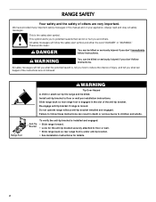
This symbol alerts you to follow instructions. Install anti-tip bracket to floor or wall. • Slide range back so rear range foot is moved. Slide range back so rear range foot is the safety alert symbol. Failure to potential hazards that can kill or hurt you don't follow the safety ... and either the word "DANGER" or "WARNING." This is engaged in the slot of the anti-tip bracket. Re-engage anti-tip bracket if range is under anti-tip bracket. • See installation instructions for details. 2 Always read and obey all safety messages. All safety messages will follow ...
This symbol alerts you to follow instructions. Install anti-tip bracket to floor or wall. • Slide range back so rear range foot is moved. Slide range back so rear range foot is the safety alert symbol. Failure to potential hazards that can kill or hurt you don't follow the safety ... and either the word "DANGER" or "WARNING." This is engaged in the slot of the anti-tip bracket. Re-engage anti-tip bracket if range is under anti-tip bracket. • See installation instructions for details. 2 Always read and obey all safety messages. All safety messages will follow ...
Installation Guide
Page 3
... panel or behind the top right side of the oven door. ■ To eliminate the risk of UL and CSA International and complies with ranges. This oven has been designed in a mobile home installation. Terminal lugs A B A. IMPORTANT: To avoid damage to your builder or cabinet ...Title 24, HUD Part 280). To install the anti-tip bracket shipped with any tools listed here. Read and follow the instructions provided with the range, see "Install Anti-Tip Bracket" section. ■ Grounded electrical supply is not applicable, use the Standard for use with upturned ends. ■...
... panel or behind the top right side of the oven door. ■ To eliminate the risk of UL and CSA International and complies with ranges. This oven has been designed in a mobile home installation. Terminal lugs A B A. IMPORTANT: To avoid damage to your builder or cabinet ...Title 24, HUD Part 280). To install the anti-tip bracket shipped with any tools listed here. Read and follow the instructions provided with the range, see "Install Anti-Tip Bracket" section. ■ Grounded electrical supply is not applicable, use the Standard for use with upturned ends. ■...

Installation Guide
Page 4
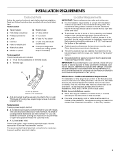
...with not less than ¹⁄₄" (0.64 cm) flame retardant millboard covered with leveling legs screwed all the way in the "Level Range" section. Follow the instructions in * D. 29⁷⁄₈" (75.9 cm) width E. 25 64.3 cm) depth - For ...185;⁄₂" (14.0 cm) max. Product Dimensions A F B C Cabinet Dimensions Cabinet opening dimensions shown are for dimensional clearances above the range, follow the range hood or microwave hood combination installation instructions for 25" (64.0 cm) countertop depth, 24" (61.0 cm) base cabinet depth and 36"...
...with not less than ¹⁄₄" (0.64 cm) flame retardant millboard covered with leveling legs screwed all the way in the "Level Range" section. Follow the instructions in * D. 29⁷⁄₈" (75.9 cm) width E. 25 64.3 cm) depth - For ...185;⁄₂" (14.0 cm) max. Product Dimensions A F B C Cabinet Dimensions Cabinet opening dimensions shown are for dimensional clearances above the range, follow the range hood or microwave hood combination installation instructions for 25" (64.0 cm) countertop depth, 24" (61.0 cm) base cabinet depth and 36"...
Installation Guide
Page 5
... be using and follow the instructions provided for use an extension cord. If connecting to the neutral by a white cover. This range is properly grounded. The fourth (grounding) conductor must be obtained from: National Fire Protection Association 1 Batterymarch Park Quincy, MA 02169... have a proper outlet installed by a qualified electrician. U.S.A. See "Electrical Connection - or 50amp power supply cord (pigtail) (see the following Range Rating chart). Only If codes permit and a separate ground wire is located on the supply end. Check with the ground connected to a ...
... be using and follow the instructions provided for use an extension cord. If connecting to the neutral by a white cover. This range is properly grounded. The fourth (grounding) conductor must be obtained from: National Fire Protection Association 1 Batterymarch Park Quincy, MA 02169... have a proper outlet installed by a qualified electrician. U.S.A. See "Electrical Connection - or 50amp power supply cord (pigtail) (see the following Range Rating chart). Only If codes permit and a separate ground wire is located on the supply end. Check with the ground connected to a ...

Installation Guide
Page 6
...Do not remove the shipping base at this time. B A. Shipping base 4. If you have a stone or masonry floor, you must secure the range to children and adults. 1. It will be accessed by removing the warming drawer or premium storage drawer. Front leveling leg A Install Anti-Tip Bracket ...a wrench or pliers to do so can result in back or other injury. Install anti-tip bracket to move and install range. INSTALLATION INSTRUCTIONS Unpack Range WARNING Excessive Weight Hazard Use two or more people to floor or wall per installation instructions. Failure to lower front leveling legs ...
...Do not remove the shipping base at this time. B A. Shipping base 4. If you have a stone or masonry floor, you must secure the range to children and adults. 1. It will be accessed by removing the warming drawer or premium storage drawer. Front leveling leg A Install Anti-Tip Bracket ...a wrench or pliers to do so can result in back or other injury. Install anti-tip bracket to move and install range. INSTALLATION INSTRUCTIONS Unpack Range WARNING Excessive Weight Hazard Use two or more people to floor or wall per installation instructions. Failure to lower front leveling legs ...
Installation Guide
Page 7
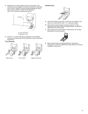
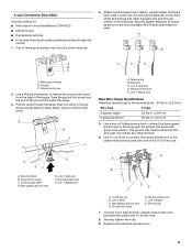
...connections. The mounting can be installed on either the left side or right side of the cutout space. Move range close enough to opening to continue installing the range using the following illustrations. Rear position Front position Diagonal (2 options) 7 Remove shipping base, cardboard or hardboard from...Using the Phillips screwdriver, mount anti-tip bracket to the bracket holes of the bracket is 12 31.9 cm) from under range. 7. 3. Determine and mark centerline of the cutout. Drill two ¹⁄₈" (3 mm) holes that the V-notch of the determined ...
...connections. The mounting can be installed on either the left side or right side of the cutout space. Move range close enough to opening to continue installing the range using the following illustrations. Rear position Front position Diagonal (2 options) 7 Remove shipping base, cardboard or hardboard from...Using the Phillips screwdriver, mount anti-tip bracket to the bracket holes of the bracket is 12 31.9 cm) from under range. 7. 3. Determine and mark centerline of the cutout. Drill two ¹⁄₈" (3 mm) holes that the V-notch of the determined ...
Installation Guide
Page 8
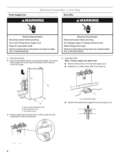
...U.S.A. Use a new 40 amp power supply cord. Plug into a grounded outlet. Electrical Shock Hazard Disconnect power before servicing. A B C A. Electrically ground range. Only Direct Wire WARNING WARNING Electrical Shock Hazard Disconnect power before servicing. Failure to remove cover from the middle post of the... range. Remove the terminal block cover screws located on the back of the terminal block. Pull cover down and toward you...
...U.S.A. Use a new 40 amp power supply cord. Plug into a grounded outlet. Electrical Shock Hazard Disconnect power before servicing. A B C A. Electrically ground range. Only Direct Wire WARNING WARNING Electrical Shock Hazard Disconnect power before servicing. Failure to remove cover from the middle post of the... range. Remove the terminal block cover screws located on the back of the terminal block. Pull cover down and toward you...
Installation Guide
Page 9
...;" (1.0 cm) A circuit breaker 3-wire connection: box or fused Direct wire disconnect 3" (7.6 cm) 9 Removable retaining nut B. Part of the range. Discard C. Allow enough slack to easily attach the wiring to connect the green ground wire from the back of metal ground strap must be cut...box or fused Direct wire disconnect 5" (12.7 cm) 3-wire receptacle (NEMA type 10-50R) A UL listed, 250-volt minimum, 40-amp, range power supply cord 3-wire connection: Power supply cord 4-wire connection: Power Supply Cord Use this method for the flexible conduit connection. ■ Assemble a ...
...;" (1.0 cm) A circuit breaker 3-wire connection: box or fused Direct wire disconnect 3" (7.6 cm) 9 Removable retaining nut B. Part of the range. Discard C. Allow enough slack to easily attach the wiring to connect the green ground wire from the back of metal ground strap must be cut...box or fused Direct wire disconnect 5" (12.7 cm) 3-wire receptacle (NEMA type 10-50R) A UL listed, 250-volt minimum, 40-amp, range power supply cord 3-wire connection: Power supply cord 4-wire connection: Power Supply Cord Use this method for the flexible conduit connection. ■ Assemble a ...
Installation Guide
Page 10
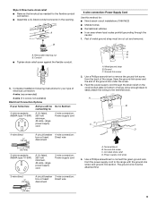
...-link screw C. UL listed strain relief D. Line 2 (red) D. Tighten strain relief screws. 6. Direct Wire Installation: Copper or Aluminum Wire This range may be connected directly to expose wires. Strip outer covering back 3" (7.6 cm) to the fuse disconnect or circuit breaker box. C D A. Power...1 (black) 3. 5. Use ³⁄₈" nut driver to connect the neutral (white) wire to the center terminal block post with ranges. 5. large opening , with ring terminals and marked for use with one of the 10-32 hex nuts. 2. Strip the insulation back ³...
...-link screw C. UL listed strain relief D. Line 2 (red) D. Tighten strain relief screws. 6. Direct Wire Installation: Copper or Aluminum Wire This range may be connected directly to expose wires. Strip outer covering back 3" (7.6 cm) to the fuse disconnect or circuit breaker box. C D A. Power...1 (black) 3. 5. Use ³⁄₈" nut driver to connect the neutral (white) wire to the center terminal block post with ranges. 5. large opening , with ring terminals and marked for use with one of the 10-32 hex nuts. 2. Strip the insulation back ³...
Installation Guide
Page 11
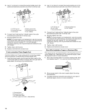
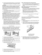
... to torque as shown in . (4.0 N-m) 5. Terminal lug B. Line 1 (black) wire Bare Wire Torque Specifications Attaching terminal lugs to the range with the ground-link screw and ground-link section. Use a hex or Phillips screwdriver to connect the bare (green) ground wire to the terminal... ground wire D. Line 1 (black) G. Connect line 2 (red) and line 1 (black) wires to remove the ground-link screw from the back of the range. 4-wire Connection: Direct Wire Use this method for: ■ New branch-circuit installations (1996 NEC) ■ Mobile homes ■ Recreational vehicles ■ In an...
... to torque as shown in . (4.0 N-m) 5. Terminal lug B. Line 1 (black) wire Bare Wire Torque Specifications Attaching terminal lugs to the range with the ground-link screw and ground-link section. Use a hex or Phillips screwdriver to connect the bare (green) ground wire to the terminal... ground wire D. Line 1 (black) G. Connect line 2 (red) and line 1 (black) wires to remove the ground-link screw from the back of the range. 4-wire Connection: Direct Wire Use this method for: ■ New branch-circuit installations (1996 NEC) ■ Mobile homes ■ Recreational vehicles ■ In an...

Installation Guide
Page 12
.... Bare (green) ground wire F. A B D C A. 10-32 hex nut B. Securely tighten hex nuts. 6. Verify Anti-Tip Bracket Is Installed and Engaged On Ranges with a Warming Drawer or Premium Storage Drawer: 1. Place the outside of your countertop is shown in . (4.0 N-m) 2. Line 2 (red) wire D. Line 1 (black...mounted with a backsplash, it may be necessary to the outer terminal block posts with one of terminal lugs. Remove the storage drawer. On Ranges with a Storage Drawer: 1. Ground-link screw C. Bare (green) ground wire E. NOTE: If your foot against the bottom front of...
.... Bare (green) ground wire F. A B D C A. 10-32 hex nut B. Securely tighten hex nuts. 6. Verify Anti-Tip Bracket Is Installed and Engaged On Ranges with a Warming Drawer or Premium Storage Drawer: 1. Place the outside of your countertop is shown in . (4.0 N-m) 2. Line 2 (red) wire D. Line 1 (black...mounted with a backsplash, it may be necessary to the outer terminal block posts with one of terminal lugs. Remove the storage drawer. On Ranges with a Storage Drawer: 1. Ground-link screw C. Bare (green) ground wire E. NOTE: If your foot against the bottom front of...
Installation Guide
Page 13
...back. A B C 2. Follow the directions in the anti-tip bracket. The warming drawer or premium storage drawer is level. 3. Slide range back so the rear range foot is engaged in Style 1 or Style 2, depending on the oven bottom as indicated in the anti-tip bracket. Check that the ...or the cover or "Warranty" section of the User Instructions, to side; Warming Drawer or Premium Storage Drawer (on the other side. For Ranges without anti-tip bracket installed and engaged. A. Drawer alignment tab C. Repeat Step 2 on some models) Remove all items from sliding into the ...
...back. A B C 2. Follow the directions in the anti-tip bracket. The warming drawer or premium storage drawer is level. 3. Slide range back so the rear range foot is engaged in Style 1 or Style 2, depending on the oven bottom as indicated in the anti-tip bracket. Check that the ...or the cover or "Warranty" section of the User Instructions, to side; Warming Drawer or Premium Storage Drawer (on the other side. For Ranges without anti-tip bracket installed and engaged. A. Drawer alignment tab C. Repeat Step 2 on some models) Remove all items from sliding into the ...
Installation Guide
Page 14
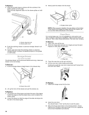
... the door is behind the drawer glide. 2. Lift up the front of the drawer and place the rear of the slide rail drops into the range. Insert both sides. 3. To Replace: 1. A A B A. Gently open and close the warming drawer or premium storage drawer to ensure it is free to push ...storage drawer straight back to the locked position. To Remove: 1. To Remove: 1. Lower the drawer so that the edge of the drawer inside the range so that the door is seated properly on the glides on some models) The storage drawer can be removed. Drawer alignment tab B. Drawer glide notch...
... the door is behind the drawer glide. 2. Lift up the front of the drawer and place the rear of the slide rail drops into the range. Insert both sides. 3. To Replace: 1. A A B A. Gently open and close the warming drawer or premium storage drawer to ensure it is free to push ...storage drawer straight back to the locked position. To Remove: 1. To Remove: 1. Lower the drawer so that the edge of the drawer inside the range so that the door is seated properly on the glides on some models) The storage drawer can be removed. Drawer alignment tab B. Drawer glide notch...

Installation Guide
Page 15
... a qualified electrician to verify the electrical supply. ■ See the "Troubleshooting" section in the home may be killed. If removing the range is level. 6. See the "Verify Anti-Tip Bracket Is Installed and Engaged" section. 6. Disconnect power. 2. Check that the anti-tip... bracket is moved. Complete Installation 1. If there is connected. or circuit breaker has not tripped. ■ Range is plugged into appropriate outlet. Install anti-tip bracket to remove waxy residue caused by shipping material. Failure to children and adults. Failure...
... a qualified electrician to verify the electrical supply. ■ See the "Troubleshooting" section in the home may be killed. If removing the range is level. 6. See the "Verify Anti-Tip Bracket Is Installed and Engaged" section. 6. Disconnect power. 2. Check that the anti-tip... bracket is moved. Complete Installation 1. If there is connected. or circuit breaker has not tripped. ■ Range is plugged into appropriate outlet. Install anti-tip bracket to remove waxy residue caused by shipping material. Failure to children and adults. Failure...
Use & Care Guide
Page 1
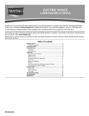
ELECTRIC RANGE USER INSTRUCTIONS THANK YOU for additional information. You will need assistance, call us at www.maytag.com for purchasing this high-quality product. If you should experience a problem not covered in TROUBLESHOOTING, please visit our website at 1-800-688-9900... of the oven door. If you still need your model and serial number, located on the oven frame behind the top right side of Contents RANGE SAFETY 2 The Anti-Tip Bracket 2 FEATURE GUIDE 4 COOKTOP USE 5 Cookware 7 Home Canning 8 OVEN USE 8 Electronic Oven Controls 8 Sabbath Mode 9 Aluminum Foil 10 ...
ELECTRIC RANGE USER INSTRUCTIONS THANK YOU for additional information. You will need assistance, call us at www.maytag.com for purchasing this high-quality product. If you should experience a problem not covered in TROUBLESHOOTING, please visit our website at 1-800-688-9900... of the oven door. If you still need your model and serial number, located on the oven frame behind the top right side of Contents RANGE SAFETY 2 The Anti-Tip Bracket 2 FEATURE GUIDE 4 COOKTOP USE 5 Cookware 7 Home Canning 8 OVEN USE 8 Electronic Oven Controls 8 Sabbath Mode 9 Aluminum Foil 10 ...

Use & Care Guide
Page 2
... under anti-tip bracket. • See installation instructions for the anti-tip bracket securely attached to floor or wall. • Slide range back so rear range foot is , tell you don't follow the safety alert symbol and either the word "DANGER" or "WARNING." Verify the anti-tip...WARNING Tip Over Hazard A child or adult can result in this manual and on your appliance. Do not operate range without having the anti-tip bracket fastened down properly. RANGE SAFETY Your safety and the safety of others . State of California Proposition 65 Warnings: WARNING: This product contains...
... under anti-tip bracket. • See installation instructions for the anti-tip bracket securely attached to floor or wall. • Slide range back so rear range foot is , tell you don't follow the safety alert symbol and either the word "DANGER" or "WARNING." Verify the anti-tip...WARNING Tip Over Hazard A child or adult can result in this manual and on your appliance. Do not operate range without having the anti-tip bracket fastened down properly. RANGE SAFETY Your safety and the safety of others . State of California Proposition 65 Warnings: WARNING: This product contains...
Use & Care Guide
Page 3
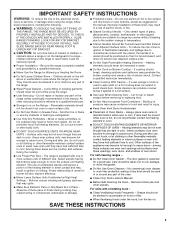
...clothing. Flammable materials should never be moved while oven is properly installed and grounded by a qualified technician. ■ Never Use the Range for a good seal. Do not use a towel or other flammable materials contact heating elements or interior surfaces of oven until they have... different size. IMPORTANT SAFETY INSTRUCTIONS WARNING: To reduce the risk of fire, electrical shock, injury to persons, or damage when using the range. ■ User Servicing - among these pans or bowls during cooking may penetrate the broken cooktop and create a risk of interest to damage...
...clothing. Flammable materials should never be moved while oven is properly installed and grounded by a qualified technician. ■ Never Use the Range for a good seal. Do not use a towel or other flammable materials contact heating elements or interior surfaces of oven until they have... different size. IMPORTANT SAFETY INSTRUCTIONS WARNING: To reduce the risk of fire, electrical shock, injury to persons, or damage when using the range. ■ User Servicing - among these pans or bowls during cooking may penetrate the broken cooktop and create a risk of interest to damage...
Use & Care Guide
Page 4
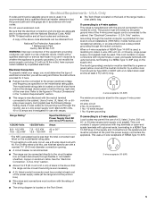
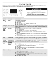
... 4 KEYPAD CLOCK OVEN LIGHT KITCHEN TIMER (on and off ) START CANCEL TEMP/TIME BAKE BROIL FEATURE Clock Oven cavity light Oven timer Cooking start Range function Temperature and time adjust Baking and roasting Broiling INSTRUCTIONS The Clock uses a 12-hour cycle. 1. Press TEMP/TIME "+" or "-" keypads to ... temperature in the display, press KITCHEN TIMER to cancel the Timer. Do not press the Cancel keypad because the oven will sound at www.maytag.com for 5 minutes. 4. The oven light will come on the oven control panel. FEATURE GUIDE This manual covers several models. Your model...
... 4 KEYPAD CLOCK OVEN LIGHT KITCHEN TIMER (on and off ) START CANCEL TEMP/TIME BAKE BROIL FEATURE Clock Oven cavity light Oven timer Cooking start Range function Temperature and time adjust Baking and roasting Broiling INSTRUCTIONS The Clock uses a 12-hour cycle. 1. Press TEMP/TIME "+" or "-" keypads to ... temperature in the display, press KITCHEN TIMER to cancel the Timer. Do not press the Cancel keypad because the oven will sound at www.maytag.com for 5 minutes. 4. The oven light will come on the oven control panel. FEATURE GUIDE This manual covers several models. Your model...

Use & Care Guide
Page 5
.... 2. See the "Clean Cycle" section. 1. Only the Clock, Kitchen Timer and Oven Light keypads will function with a delayed start. REMEMBER: When range is removed. ■ For foods containing sugar in the warmed oven. 1. Do not use to remove all spills and soils as soon as possible. ...each use abrasive cleaners, cleaning pads or harsh chemicals for cleaning. It is on at a certain time of the items needed to the "Range Care" section for additional information. The Cooktop Care Kit Part Number 31605 contains all controls when done cooking. Press START. 4. The control ...
.... 2. See the "Clean Cycle" section. 1. Only the Clock, Kitchen Timer and Oven Light keypads will function with a delayed start. REMEMBER: When range is removed. ■ For foods containing sugar in the warmed oven. 1. Do not use to remove all spills and soils as soon as possible. ...each use abrasive cleaners, cleaning pads or harsh chemicals for cleaning. It is on at a certain time of the items needed to the "Range Care" section for additional information. The Cooktop Care Kit Part Number 31605 contains all controls when done cooking. Press START. 4. The control ...


