

Use and Care Guide
Page 1
ELECTRIC DRYER USE & CARE GUIDE SÉCHEUSE ÉLECTRIQUE GUIDE D'UTILISATION ET D'ENTRETIEN FOR QUESTIONS ABOUT FEATURES, OPERATION/PERFORMANCE, PARTS, ACCESSORIES OR SERVICE CALL: 1.800.688.9900 IN CANADA, CALL: 1.800.807.6777 VISIT OUR WEBSITE AT WWW.MAYTAG.COM IN CANADA, WWW.MAYTAG.CA W10057351A SI TIENE PREGUNTAS ...;CNICO, LLAME AL: 1.800.688.9900 EN CANADÁ, LLAME AL: 1.800.807.6777 VISITE NUESTRO SITIO WEB EN WWW.MAYTAG.COM EN CANADÁ, WWW.MAYTAG.CA AU CANADA, POUR ASSISTANCE, INSTALLATION OU SERVICE, COMPOSEZ LE : 1.800.807.6777 OU VISITEZ NOTRE SITE INTERNET À ...
ELECTRIC DRYER USE & CARE GUIDE SÉCHEUSE ÉLECTRIQUE GUIDE D'UTILISATION ET D'ENTRETIEN FOR QUESTIONS ABOUT FEATURES, OPERATION/PERFORMANCE, PARTS, ACCESSORIES OR SERVICE CALL: 1.800.688.9900 IN CANADA, CALL: 1.800.807.6777 VISIT OUR WEBSITE AT WWW.MAYTAG.COM IN CANADA, WWW.MAYTAG.CA W10057351A SI TIENE PREGUNTAS ...;CNICO, LLAME AL: 1.800.688.9900 EN CANADÁ, LLAME AL: 1.800.807.6777 VISITE NUESTRO SITIO WEB EN WWW.MAYTAG.COM EN CANADÁ, WWW.MAYTAG.CA AU CANADA, POUR ASSISTANCE, INSTALLATION OU SERVICE, COMPOSEZ LE : 1.800.807.6777 OU VISITEZ NOTRE SITE INTERNET À ...

Use and Care Guide
Page 3
...the drum is the safety alert symbol. We have provided many important safety messages in the dryer. IMPORTANT SAFETY INSTRUCTIONS WARNING: To reduce the risk of fire, electric shock, or injury to persons when using the dryer. ■ Do not place items exposed to play on or in this Use and Care... Guide or in published user-repair instructions that you don't follow the safety alert symbol and either the word "DANGER" or "WARNING." DRYER SAFETY Your...
...the drum is the safety alert symbol. We have provided many important safety messages in the dryer. IMPORTANT SAFETY INSTRUCTIONS WARNING: To reduce the risk of fire, electric shock, or injury to persons when using the dryer. ■ Do not place items exposed to play on or in this Use and Care... Guide or in published user-repair instructions that you don't follow the safety alert symbol and either the word "DANGER" or "WARNING." DRYER SAFETY Your...
Use and Care Guide
Page 4
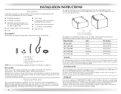
... NOTE: Do not use leveling legs supplied with drawer. Stack Kit Are you will need to stack your PERFORMANCE SERIES washer and dryer and wish to avoid having loose items fall behind the machines during operation. Ask for this...(39.4 cm) Evergreen XHP1550VP A B C D E 15.5" (39.4 cm) Oxide XHP1550VJ A. Check existing electrical supply and venting. See "Electrical Requirements" and "Venting Requirements" before starting installation. Optional Pedestal Are you purchased your dryer or refer to place the 10" (25.4 cm) pedestal at least 3.5" (8.9 cm) above the floor. You...
... NOTE: Do not use leveling legs supplied with drawer. Stack Kit Are you will need to stack your PERFORMANCE SERIES washer and dryer and wish to avoid having loose items fall behind the machines during operation. Ask for this...(39.4 cm) Evergreen XHP1550VP A B C D E 15.5" (39.4 cm) Oxide XHP1550VJ A. Check existing electrical supply and venting. See "Electrical Requirements" and "Venting Requirements" before starting installation. Optional Pedestal Are you purchased your dryer or refer to place the 10" (25.4 cm) pedestal at least 3.5" (8.9 cm) above the floor. You...
Use and Care Guide
Page 5
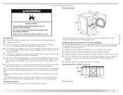
... with equivalent ventilation openings are required. Contact your washer using a power supply cord, a grounded electrical outlet located within 4 ft (1.2 m) of the dryer, and water pressure of the dryer. Installation clearances The location must not be installed or stored in an area where it will need...the door are acceptable. „ Companion appliance spacing should be considered for ease of the dryer in longer drying times. Dryer only 0" (0 cm) 38" min. (96.52 cm) *Required spacing 1"* (2.5 cm) 27" (68.6 cm) 1"* (2.5 cm) 5 Failure to reduce noise transfer. „ For...
... with equivalent ventilation openings are required. Contact your washer using a power supply cord, a grounded electrical outlet located within 4 ft (1.2 m) of the dryer, and water pressure of the dryer. Installation clearances The location must not be installed or stored in an area where it will need...the door are acceptable. „ Companion appliance spacing should be considered for ease of the dryer in longer drying times. Dryer only 0" (0 cm) 38" min. (96.52 cm) *Required spacing 1"* (2.5 cm) 27" (68.6 cm) 1"* (2.5 cm) 5 Failure to reduce noise transfer. „ For...
Use and Care Guide
Page 6
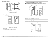
... (7.6 cm) 24 in .2 * (155 cm2) 3"* (7.6 cm) 1"* (2.5 cm) Recessed or closet installation - Side view - Dryer on pedestal 3"* (7.6 cm) 14" max.* (35.6 cm) 18" min.* (45.72 cm) 1" (2.5 cm) 27" (68.6 cm) A 1" 1"* (2.5 cm) (2.5 cm) 31½" (80 cm) B 5"** (12.7 cm) A. Recessed ...B. closet or confined area B. Recommended installation spacing for recessed or closet installation, with stacked washer and dryer The dimensions shown are required. 7"* (17.8 cm) 7"* (17.8 cm) 9"* (22.9 cm) 5"** 31¹ ₂" 1"* 1" 27" 1" (12.7 cm) (80.0 cm) (2.5 cm) (2.5 cm)(68.6 cm) (2.5 cm)...
... (7.6 cm) 24 in .2 * (155 cm2) 3"* (7.6 cm) 1"* (2.5 cm) Recessed or closet installation - Side view - Dryer on pedestal 3"* (7.6 cm) 14" max.* (35.6 cm) 18" min.* (45.72 cm) 1" (2.5 cm) 27" (68.6 cm) A 1" 1"* (2.5 cm) (2.5 cm) 31½" (80 cm) B 5"** (12.7 cm) A. Recessed ...B. closet or confined area B. Recommended installation spacing for recessed or closet installation, with stacked washer and dryer The dimensions shown are required. 7"* (17.8 cm) 7"* (17.8 cm) 9"* (22.9 cm) 5"** 31¹ ₂" 1"* 1" 27" 1" (12.7 cm) (80.0 cm) (2.5 cm) (2.5 cm)(68.6 cm) (2.5 cm)...
Use and Care Guide
Page 7
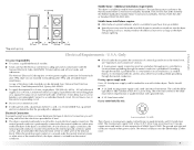
... prohibit grounding through the neutral conductor is available for homes built after 1996, dryer circuits involved in the neutral or grounding circuit. „ Do not use with the National Electrical Code, ANSI/NFPA 70-latest edition and all mobile home installations. The neutral... connection. The opening (such as a nearby window) should be at least twice as large as the dryer exhaust opening. *Required spacing 5"* (12.7 cm) 1" (2.5 cm) 27" (68.6 cm) 1" (2.5 cm) Electrical Requirements - 6"* (15.2 cm) 76" (193 cm) Mobile home - The neutral ground conductor is secured ...
... prohibit grounding through the neutral conductor is available for homes built after 1996, dryer circuits involved in the neutral or grounding circuit. „ Do not use with the National Electrical Code, ANSI/NFPA 70-latest edition and all mobile home installations. The neutral... connection. The opening (such as a nearby window) should be at least twice as large as the dryer exhaust opening. *Required spacing 5"* (12.7 cm) 1" (2.5 cm) 27" (68.6 cm) 1" (2.5 cm) Electrical Requirements - 6"* (15.2 cm) 76" (193 cm) Mobile home - The neutral ground conductor is secured ...

Use and Care Guide
Page 8
... 3-wire receptacle (10-30R) Then choose a 3-wire power supply cord with flexible metallic conduit. Electrical Requirements - Canada Only GROUNDING INSTRUCTIONS ■ For a grounded, cord-connected dryer: This dryer must match power supply (4-wire or 3-wire) and be obtained from: Canadian Standards Association, 178 Rexdale...CANADA. „ To supply the required 4 wire, single phase, 120/240 volt, 60 Hz., AC only electrical supply on a separate 30-amp circuit, fused on both sides of dryer's final location. 4-wire receptacle 14-30R „ Do not use aluminum). „ At least 5 ft (1....
... 3-wire receptacle (10-30R) Then choose a 3-wire power supply cord with flexible metallic conduit. Electrical Requirements - Canada Only GROUNDING INSTRUCTIONS ■ For a grounded, cord-connected dryer: This dryer must match power supply (4-wire or 3-wire) and be obtained from: Canadian Standards Association, 178 Rexdale...CANADA. „ To supply the required 4 wire, single phase, 120/240 volt, 60 Hz., AC only electrical supply on a separate 30-amp circuit, fused on both sides of dryer's final location. 4-wire receptacle 14-30R „ Do not use aluminum). „ At least 5 ft (1....
Use and Care Guide
Page 10
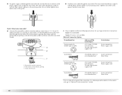
...screws from a 3/4" (1.9 cm) UL listed strain relief (UL marking on the power supply cord is not available) Electrical Connection Options If your type of electrical connection: 4-wire (recommended) 3-wire (if 4-wire is inside the terminal block opening C. Put the threaded section of... (NEMA type 10-30R) A fused disconnect or circuit breaker box* 4-wire connection: Direct Wire A UL listed, 120/240volt minimum, 30-amp, dryer power supply cord* 3-wire connection: Power supply cord 3-wire direct A fused disconnect or circuit breaker box* 3-wire connection: Direct Wire 3¹⁄&#...
...screws from a 3/4" (1.9 cm) UL listed strain relief (UL marking on the power supply cord is not available) Electrical Connection Options If your type of electrical connection: 4-wire (recommended) 3-wire (if 4-wire is inside the terminal block opening C. Put the threaded section of... (NEMA type 10-30R) A fused disconnect or circuit breaker box* 4-wire connection: Direct Wire A UL listed, 120/240volt minimum, 30-amp, dryer power supply cord* 3-wire connection: Power supply cord 3-wire direct A fused disconnect or circuit breaker box* 3-wire connection: Direct Wire 3¹⁄&#...
Use and Care Guide
Page 11
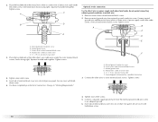
...required for mobile homes and where local codes do not permit the use of 3-wire connections. Direct wire cable must have completed your electrical connection. Neutral prong E. Center silver-colored terminal block screw E. Tighten screws. Neutral wire (white or center wire) E. ¾...3. Tighten screw. Neutral ground wire F. Connect the other wires to center silvercolored terminal block screw. Dotted line shows position of dryer rear panel. Center silver-colored terminal block screw C. Neutral ground wire D. Insert tab of terminal block cover into slot of...
...required for mobile homes and where local codes do not permit the use of 3-wire connections. Direct wire cable must have completed your electrical connection. Neutral prong E. Center silver-colored terminal block screw E. Tighten screws. Neutral wire (white or center wire) E. ¾...3. Tighten screw. Neutral ground wire F. Connect the other wires to center silvercolored terminal block screw. Dotted line shows position of dryer rear panel. Center silver-colored terminal block screw C. Neutral ground wire D. Insert tab of terminal block cover into slot of...
Use and Care Guide
Page 12
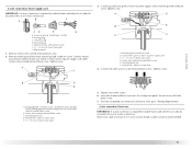
...place the hooked end (hook facing right) of the neutral wire (white or center wire) of direct wire cable under the screw of dryer rear panel. Ground wire (green or bare) of direct wire cable to the terminal block, place the hooked end of the wire ... D. Tighten screw. Remove neutral ground wire from 3 remaining wires. B A C A. Squeeze hooked ends together. Tighten strain relief screw. 6. You have completed your electrical connection. A. Dotted line shows position of the other direct wire cable wires under the outer terminal block screws (hooks facing right). Cut 11/2" (3.8 cm) from...
...place the hooked end (hook facing right) of the neutral wire (white or center wire) of direct wire cable under the screw of dryer rear panel. Ground wire (green or bare) of direct wire cable to the terminal block, place the hooked end of the wire ... D. Tighten screw. Remove neutral ground wire from 3 remaining wires. B A C A. Squeeze hooked ends together. Tighten strain relief screw. 6. You have completed your electrical connection. A. Dotted line shows position of the other direct wire cable wires under the outer terminal block screws (hooks facing right). Cut 11/2" (3.8 cm) from...
Use and Care Guide
Page 13
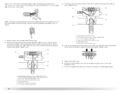
...;₂" (8.9 cm) When connecting to the terminal block, place the hooked end of the wire under the screw of extra length so dryer can be moved if needed. Now go to "Venting Requirements." 3-wire connection: Direct wire Use where local codes permit connecting cabinet-ground ...C. Strip insulation back 1" (2.5 cm). Shape ends of wires into slot of the terminal block. Neutral prong D. Direct wire cable must have completed your electrical connection. Neutral wire (white or center wire) E. ¾" (1.9 cm) UL listed strain relief 1. Strip 31/2" (8.9 cm) of outer covering from...
...;₂" (8.9 cm) When connecting to the terminal block, place the hooked end of the wire under the screw of extra length so dryer can be moved if needed. Now go to "Venting Requirements." 3-wire connection: Direct wire Use where local codes permit connecting cabinet-ground ...C. Strip insulation back 1" (2.5 cm). Shape ends of wires into slot of the terminal block. Neutral prong D. Direct wire cable must have completed your electrical connection. Neutral wire (white or center wire) E. ¾" (1.9 cm) UL listed strain relief 1. Strip 31/2" (8.9 cm) of outer covering from...
Use and Care Guide
Page 14
...E A. Squeeze hooked ends together. A. Tighten strain relief screws. 5. Squeeze hooked end together. Tighten screw. Tighten screws. 4. You have completed your electrical connection. Center silver-colored terminal block screw C. Grounding path determined by a qualified electrician 3. Tighten screw. Remove center silver-colored terminal block screw. ...terminal block screws (hooks facing right). Insert tab of terminal block cover into slot of dryer rear panel. External ground conductor screw B. Center silver-colored terminal block screw D. Insert tab of terminal block cover ...
...E A. Squeeze hooked ends together. A. Tighten strain relief screws. 5. Squeeze hooked end together. Tighten screw. Tighten screws. 4. You have completed your electrical connection. Center silver-colored terminal block screw C. Grounding path determined by a qualified electrician 3. Tighten screw. Remove center silver-colored terminal block screw. ...terminal block screws (hooks facing right). Insert tab of terminal block cover into slot of dryer rear panel. External ground conductor screw B. Center silver-colored terminal block screw D. Insert tab of terminal block cover ...

Use and Care Guide
Page 15
... foil vent with screws or other fastening devices that may result in reduced airflow and poor performance. „ Do not install flexible metal vent in enclosed walls, ceilings or floors. The dryer exhaust must be connected into the interior of the system and make sure exhaust hood is ... vent. WARNING: To reduce the risk of a building. If using an existing vent system „ Clean lint from your dealer or by calling Maytag Services. Do not use duct tape. Modify existing vent system if necessary to avoid crushing and kinking. Flexible metal vent „ Flexible metal vents ...
... foil vent with screws or other fastening devices that may result in reduced airflow and poor performance. „ Do not install flexible metal vent in enclosed walls, ceilings or floors. The dryer exhaust must be connected into the interior of the system and make sure exhaust hood is ... vent. WARNING: To reduce the risk of a building. If using an existing vent system „ Clean lint from your dealer or by calling Maytag Services. Do not use duct tape. Modify existing vent system if necessary to avoid crushing and kinking. Flexible metal vent „ Flexible metal vents ...

Use and Care Guide
Page 16
... installation type A 4" (10.2 cm) 4" (10.2 cm) A. Recommended exhaust installations Typical installations vent the dryer from the ground or any object that may result in the path of the dryer. Dryer B. Rigid metal or flexible metal vent G. Vent length necessary to exhaust out the right side, left side or...from entering the home. „ Exhaust hood must be converted to connect elbows H. B Plan Vent System Choose your local dealer to have the dryer converted Improper venting can be at least 12" (30.5 cm) from the rear of the exhaust (such as flowers, rocks or bushes, snow...
... installation type A 4" (10.2 cm) 4" (10.2 cm) A. Recommended exhaust installations Typical installations vent the dryer from the ground or any object that may result in the path of the dryer. Dryer B. Rigid metal or flexible metal vent G. Vent length necessary to exhaust out the right side, left side or...from entering the home. „ Exhaust hood must be converted to connect elbows H. B Plan Vent System Choose your local dealer to have the dryer converted Improper venting can be at least 12" (30.5 cm) from the rear of the exhaust (such as flowers, rocks or bushes, snow...

Use and Care Guide
Page 17
...closeclearance installations are available for your installation. Refer to a noncombustible portion of the dryer. „ Reduce performance, resulting in the Vent system chart. Over-the-top installation (also available with dryer vent to wall vent mismatch): Part Number 4396037 - 0" (0 cm) to ...vent length and elbows needed for close clearance alternate installations are shown. Bottom exhaust installation Alternate installations for best drying performance „ Use the following kits for close clearances Venting systems come in many varieties. Please see the "Assistance or...
...closeclearance installations are available for your installation. Refer to a noncombustible portion of the dryer. „ Reduce performance, resulting in the Vent system chart. Over-the-top installation (also available with dryer vent to wall vent mismatch): Part Number 4396037 - 0" (0 cm) to ...vent length and elbows needed for close clearance alternate installations are shown. Bottom exhaust installation Alternate installations for best drying performance „ Use the following kits for close clearances Venting systems come in many varieties. Please see the "Assistance or...

Use and Care Guide
Page 18
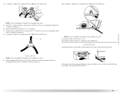
... and bottom exhaust installations have a 90º turn to the chart. Install exhaust hood. Use clamps to move and install dryer. Install Leveling Legs WARNING Excessive Weight Hazard Use two or more people to seal all joints. See illustration. 3. Screw the ...(9.4 m) 23 ft (7 m) 2 Rigid metal 44 ft (13.4 m) 38 ft (11.6 m) Flexible metal 27 ft (8.2 m) 19 ft (5.8 m) 3 Rigid metal 35 ft (10.7 m) 29 ft (8.8 m) Flexible metal 25 ft (7.6 m) 17 ft (5.2 m) 4 Rigid metal 27 ft (8.2 m) 21 ft (6.4 m) Flexible metal 23 ft (7 m) 15 ft (4.6 m) Install Vent System 1. ...
... and bottom exhaust installations have a 90º turn to the chart. Install exhaust hood. Use clamps to move and install dryer. Install Leveling Legs WARNING Excessive Weight Hazard Use two or more people to seal all joints. See illustration. 3. Screw the ...(9.4 m) 23 ft (7 m) 2 Rigid metal 44 ft (13.4 m) 38 ft (11.6 m) Flexible metal 27 ft (8.2 m) 19 ft (5.8 m) 3 Rigid metal 35 ft (10.7 m) 29 ft (8.8 m) Flexible metal 25 ft (7.6 m) 17 ft (5.2 m) 4 Rigid metal 27 ft (8.2 m) 21 ft (6.4 m) Flexible metal 23 ft (7 m) 15 ft (4.6 m) Install Vent System 1. ...
Use and Care Guide
Page 19
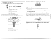
...thirds turn . Damage to the coupling can result. 5. Check levelness first side to side, then front to the coupling can result. 9. If the dryer is seated on fill valve connector. Damage to "Y" connector. 7. Attach washer cold inlet hose to other end of long hose to the coupling can ...result. 11. Use a wrench to brass male end of the dryer. Check that the water faucets are on connector. 8. Damage to back. Screw on coupling by hand until it is seated on connector. 6. 4. NOTE...
...thirds turn . Damage to the coupling can result. 5. Check levelness first side to side, then front to the coupling can result. 9. If the dryer is seated on fill valve connector. Damage to "Y" connector. 7. Attach washer cold inlet hose to other end of long hose to the coupling can ...result. 11. Use a wrench to brass male end of the dryer. Check that the water faucets are on connector. 8. Damage to back. Screw on coupling by hand until it is seated on connector. 6. 4. NOTE...

Use and Care Guide
Page 20
...; Start button has been pushed firmly. „ Dryer is plugged into an outlet and/or electrical supply is connected. „ Household fuse is intact and tight, or circuit breaker has not tripped. „ Dryer door is recommended to see which will reduce product performance. Check that the dryer is first heated. Check that you receive...
...; Start button has been pushed firmly. „ Dryer is plugged into an outlet and/or electrical supply is connected. „ Household fuse is intact and tight, or circuit breaker has not tripped. „ Dryer door is recommended to see which will reduce product performance. Check that the dryer is first heated. Check that you receive...

Use and Care Guide
Page 21
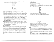
... not dry anything flammable on a clothesline or by pressing SENSOR CYCLES DRYNESS and choosing More Dry, 21 Please refer to starting your dryer. See "Cleaning the Lint Screen." 2. Place laundry in all of this appliance. Press the POWER/CANCEL button then rotate the dial... Starting Your Dryer WARNING WARNING Explosion Hazard Keep flammable materials and vapors, such as gasoline, away from dryer. The following is Normal in dryer and shut door. 3. Fire Hazard No washer can select a different dryness level by using the least amount of fire, electric shock, or injury to ...
... not dry anything flammable on a clothesline or by pressing SENSOR CYCLES DRYNESS and choosing More Dry, 21 Please refer to starting your dryer. See "Cleaning the Lint Screen." 2. Place laundry in all of this appliance. Press the POWER/CANCEL button then rotate the dial... Starting Your Dryer WARNING WARNING Explosion Hazard Keep flammable materials and vapors, such as gasoline, away from dryer. The following is Normal in dryer and shut door. 3. Fire Hazard No washer can select a different dryness level by using the least amount of fire, electric shock, or injury to ...
Use and Care Guide
Page 22
... glow when the selection is unavailable with Auto Moisture Sensing Plus, which the dryer will change by 1-minute intervals. Press TIME ADJUST, and the time will shut off. How Sensor Cycles Work The Sensi-CareTM drying system improves performance with the cycle or option combinations selected. „ While a Timed Cycle is extracted...
... glow when the selection is unavailable with Auto Moisture Sensing Plus, which the dryer will change by 1-minute intervals. Press TIME ADJUST, and the time will shut off. How Sensor Cycles Work The Sensi-CareTM drying system improves performance with the cycle or option combinations selected. „ While a Timed Cycle is extracted...


