
Installation Instructions
Page 2
DRYER SAFETY 2
DRYER SAFETY 2
Installation Instructions
Page 4
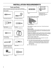
...power supply cord: Use a UL listed power supply cord kit marked for purchase from the dealer from whom you purchased your dryer. Tape measure Pliers 4 Check existing electrical supply and venting, and read "Electrical Requirements" and "Venting Requirements" before starting installation. Check ...that opens to the dryer must end in dryer drum. For further information, please reference the "Assistance or Service" section of the "Use and Care Guide". The kit ...
...power supply cord: Use a UL listed power supply cord kit marked for purchase from the dealer from whom you purchased your dryer. Tape measure Pliers 4 Check existing electrical supply and venting, and read "Electrical Requirements" and "Venting Requirements" before starting installation. Check ...that opens to the dryer must end in dryer drum. For further information, please reference the "Assistance or Service" section of the "Use and Care Guide". The kit ...
Installation Instructions
Page 5
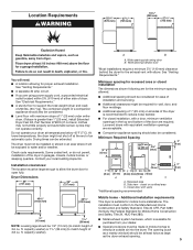
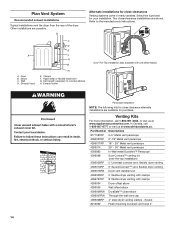
... considered for proper exhaust installation. Do not operate your local building inspector. Drying times can be large enough to allow the dryer door to the Manufactured Home Construction and Safety Standard, Title 24 CFR, Part 3280 (formerly the Federal Standard for Mobile Home..., which is suitable for recessed area or closet installation The dimensions shown following are required. See "Venting Requirements." Louvered doors with maximum slope of the dryer in .2 * (155 cm )2 1" 29" 1" 1"* 27¾" (25 mm) (737 mm) (25 mm) (25 mm) (705 mm) A B C A. Installation ...
... considered for proper exhaust installation. Do not operate your local building inspector. Drying times can be large enough to allow the dryer door to the Manufactured Home Construction and Safety Standard, Title 24 CFR, Part 3280 (formerly the Federal Standard for Mobile Home..., which is suitable for recessed area or closet installation The dimensions shown following are required. See "Venting Requirements." Louvered doors with maximum slope of the dryer in .2 * (155 cm )2 1" 29" 1" 1"* 27¾" (25 mm) (737 mm) (25 mm) (25 mm) (705 mm) A B C A. Installation ...

Installation Instructions
Page 6
...connection for use aluminum). ■■ At least 5 ft. (1.52 m) long. 6 Connect to the neutral conductor (white wire) within the dryer. The neutral ground wire is permanently connected to an individual branch circuit. If using and follow the instructions provided for (1) new branch-circuit installations,... connection you will be using a power supply cord: Use a UL listed power supply cord kit marked for homes built after 1996, dryer circuits involved in remodeling after 1996, and all local codes and ordinances. The cord should contain: ■■ A UL listed 30...
...connection for use aluminum). ■■ At least 5 ft. (1.52 m) long. 6 Connect to the neutral conductor (white wire) within the dryer. The neutral ground wire is permanently connected to an individual branch circuit. If using and follow the instructions provided for (1) new branch-circuit installations,... connection you will be using a power supply cord: Use a UL listed power supply cord kit marked for homes built after 1996, dryer circuits involved in remodeling after 1996, and all local codes and ordinances. The cord should contain: ■■ A UL listed 30...

Installation Instructions
Page 7
... to connect the exhaust vent. This connection may be used with either a power supply cord or a direct wire connection. 7 Slide the dryer until bottom of a cabinet-ground conductor to neutral wire, go to Venting Requirements. Leave enough room for 4-wire Direct Wire Connection section. ... cardboard from bottom of 3.8 cu. Choose electrical connection type Power supply cord 4-wire receptacle (NEMA Type 14-30R): Go to match height of dryer. Then go to Venting Requirements. 3-wire direct connection: Go to steps 1-2 on page 9 for power supply cord strain relief: then steps ...
... to connect the exhaust vent. This connection may be used with either a power supply cord or a direct wire connection. 7 Slide the dryer until bottom of a cabinet-ground conductor to neutral wire, go to Venting Requirements. Leave enough room for 4-wire Direct Wire Connection section. ... cardboard from bottom of 3.8 cu. Choose electrical connection type Power supply cord 4-wire receptacle (NEMA Type 14-30R): Go to match height of dryer. Then go to Venting Requirements. 3-wire direct connection: Go to steps 1-2 on page 9 for power supply cord strain relief: then steps ...

Installation Instructions
Page 8
... D. Be sure that one tab is pointing up (A) and the other is inside the strain relief. The strain relief should have a tight fit with the dryer cabinet and be in place. Remove terminal block cover Power Supply Cord Connection Power supply cord strain relief 1. Terminal block cover B. Attach power supply cord...
... D. Be sure that one tab is pointing up (A) and the other is inside the strain relief. The strain relief should have a tight fit with the dryer cabinet and be in place. Remove terminal block cover Power Supply Cord Connection Power supply cord strain relief 1. Terminal block cover B. Attach power supply cord...

Installation Instructions
Page 9
F Connect ground wire (F) (green or bare) of dryer rear panel. Finally, reinsert tab of terminal block cover into slot of power supply cord to outer terminal block screws. Secure cover with upturned ends F. 3/4" (...
F Connect ground wire (F) (green or bare) of dryer rear panel. Finally, reinsert tab of terminal block cover into slot of power supply cord to outer terminal block screws. Secure cover with upturned ends F. 3/4" (...

Installation Instructions
Page 10
... a tight fit with hold-down screw. Strip 5" (127 mm) of terminal block cover into hooks. 4. Put the threaded section of dryer rear panel. Connect remaining wires Put direct wire cable through the hole (B) below . Direct Wire Connection Direct wire strain relief 1. Tighten screws...ground wire at 5" (127 mm). Attach direct wire cable to strain relief Connect neutral wire (white or center) (C) of extra length so dryer may be in a horizontal position. For 4 wire Direct Wire Connection, continue to center terminal block screw (B). Strip insulation back 1" (25 mm...
... a tight fit with hold-down screw. Strip 5" (127 mm) of terminal block cover into hooks. 4. Put the threaded section of dryer rear panel. Connect remaining wires Put direct wire cable through the hole (B) below . Direct Wire Connection Direct wire strain relief 1. Tighten screws...ground wire at 5" (127 mm). Attach direct wire cable to strain relief Connect neutral wire (white or center) (C) of extra length so dryer may be in a horizontal position. For 4 wire Direct Wire Connection, continue to center terminal block screw (B). Strip insulation back 1" (25 mm...

Installation Instructions
Page 11
... must have 5 ft. (1.52 m) of wire under terminal block screw, facing to terminal block, place hooked end of extra length so dryer may be moved if needed. To connect wires to the right, squeeze hooked end together and tighten screw. 5. Strip 31/2" (89 mm... direct wire cable under outer terminal block screws (hooks facing right). Squeeze hooked ends together and tighten screw. 7. Shape wire ends into slot of dryer rear panel. Connect wires to external ground conductor screw (A). 5. Tighten screw. Prepare to neutral wire. 3. Connect remaining wires A B E Remove center...
... must have 5 ft. (1.52 m) of wire under terminal block screw, facing to terminal block, place hooked end of extra length so dryer may be moved if needed. To connect wires to the right, squeeze hooked end together and tighten screw. 5. Strip 31/2" (89 mm... direct wire cable under outer terminal block screws (hooks facing right). Squeeze hooked ends together and tighten screw. 7. Shape wire ends into slot of dryer rear panel. Connect wires to external ground conductor screw (A). 5. Tighten screw. Prepare to neutral wire. 3. Connect remaining wires A B E Remove center...

Installation Instructions
Page 12
Connect neutral wire B C 2. Connect remaining wires Place hooked ends of dryer rear panel. Now, go to Venting Requirements. Tighten screws. Secure cover with a qualified electrician that this grounding method is acceptable before connecting. 1....hooks facing right). Optional 3-wire Connection You must verify with hold-down screw. Now, go to Venting Requirements. 12 Tighten screw. 3. Place hooked ends of dryer rear panel. Connect external ground wire A A B E Remove center terminal block screw (B). Finally, reinsert tab of terminal block cover into slot of remaining wires...
Connect neutral wire B C 2. Connect remaining wires Place hooked ends of dryer rear panel. Now, go to Venting Requirements. Tighten screws. Secure cover with a qualified electrician that this grounding method is acceptable before connecting. 1....hooks facing right). Optional 3-wire Connection You must verify with hold-down screw. Now, go to Venting Requirements. 12 Tighten screw. 3. Place hooked ends of dryer rear panel. Connect external ground wire A A B E Remove center terminal block screw (B). Finally, reinsert tab of terminal block cover into slot of remaining wires...
Installation Instructions
Page 13
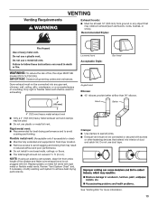
...achieve best drying performance. Flexible metal vent: (Acceptable only if accessible to clean) ■■ Must be fully extended and supported in final dryer location. ■■ Remove excess to seal all governing codes and ordinances. Clamps: ■■ Use clamps to avoid sagging and kinking that... the system and make sure exhaust hood is not plugged with rigid metal or flexible metal vents. Do not use plastic or metal foil vent. Dryer exhaust must not be used for more information. 13 Good Better 4" (102 mm) heavy metal exhaust vent ■■ Only a 4" (102...
...achieve best drying performance. Flexible metal vent: (Acceptable only if accessible to clean) ■■ Must be fully extended and supported in final dryer location. ■■ Remove excess to seal all governing codes and ordinances. Clamps: ■■ Use clamps to avoid sagging and kinking that... the system and make sure exhaust hood is not plugged with rigid metal or flexible metal vents. Do not use plastic or metal foil vent. Dryer exhaust must not be used for more information. 13 Good Better 4" (102 mm) heavy metal exhaust vent ■■ Only a 4" (102...
Installation Instructions
Page 14
... Wall D. Other installations are available for close elbow 4396007RW Through-the-wall vent cap 4396008RP 4" steel dryer venting clamps - 2 pack 8212662 Flush mounting louvered vent hood 4" 14 Two close clearances Venting systems ... (over-the-top installation) 4396009RP 5' Universal connect vent, flexible dryer venting 4396010RP 6' SecureConnect™ vent, flexible dryer venting 4396013RB Dryer vent installer's kit 4396033RP 5' flexible dryer venting with clamps 4396727RP 8' flexible dryer venting with one offset elbow) Periscope installation NOTE: The following kits...
... Wall D. Other installations are available for close elbow 4396007RW Through-the-wall vent cap 4396008RP 4" steel dryer venting clamps - 2 pack 8212662 Flush mounting louvered vent hood 4" 14 Two close clearances Venting systems ... (over-the-top installation) 4396009RP 5' Universal connect vent, flexible dryer venting 4396010RP 6' SecureConnect™ vent, flexible dryer venting 4396013RB Dryer vent installer's kit 4396033RP 5' flexible dryer venting with clamps 4396727RP 8' flexible dryer venting with one offset elbow) Periscope installation NOTE: The following kits...

Installation Instructions
Page 15
...of the mobile home structure and must fit over the exhaust hood. Exhaust systems longer than those specified will: ■■ Shorten life of dryer. ■■ Reduce performance, resulting in Vent system chart. Secure vent to seal exterior wall opening around exhaust hood. 2. Terminate the exhaust ...secure vent, because they can catch lint. 15 Do not use caulking compound to exhaust hood with 4" (102 mm) clamp. Run vent to dryer location using elbows or making turns, allow as much room as possible. ■■ Bend vent gradually to avoid kinking. ■■ ...
...of the mobile home structure and must fit over the exhaust hood. Exhaust systems longer than those specified will: ■■ Shorten life of dryer. ■■ Reduce performance, resulting in Vent system chart. Secure vent to seal exterior wall opening around exhaust hood. 2. Terminate the exhaust ...secure vent, because they can catch lint. 15 Do not use caulking compound to exhaust hood with 4" (102 mm) clamp. Run vent to dryer location using elbows or making turns, allow as much room as possible. ■■ Bend vent gradually to avoid kinking. ■■ ...
Installation Instructions
Page 16
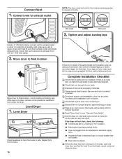
...an outlet. Connect Vent 1. Tighten and adjust leveling legs Using a 4" (102 mm) clamp, connect vent to exhaust hood with a damp cloth to final location. Dryer vent must be level for levelness. Once legs are level, make sure vent is secured to exhaust outlet in your tools. q For power supply cord... installation, plug into an outlet and/or electrical supply is closed. See "Level Dryer". Repeat from side to operate correctly. q Check that all packaging materials. Be sure vent is level. If connecting to back. 16 If...
...an outlet. Connect Vent 1. Tighten and adjust leveling legs Using a 4" (102 mm) clamp, connect vent to exhaust hood with a damp cloth to final location. Dryer vent must be level for levelness. Once legs are level, make sure vent is secured to exhaust outlet in your tools. q For power supply cord... installation, plug into an outlet and/or electrical supply is closed. See "Level Dryer". Repeat from side to operate correctly. q Check that all packaging materials. Be sure vent is level. If connecting to back. 16 If...
Installation Instructions
Page 17
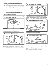
... forward off top screws Lift door until top screws in large part of hinge slot. Remove top screws from hinges Place towel on top of dryer to avoid damaging the surface. Remove screws from dryer cabinet. 4. Remove screws at top, bottom, and side of door (4 screws) that both fuses are in... over towel on top of hinges. Check that both circuit breakers have not tripped. NOTE: You may be 2 household fuses or circuit breakers for the dryer. Place towel on door seal or plastic door catches. 17 Remove bottom screws Remove screws attaching hinges to separate it from door Open...
... forward off top screws Lift door until top screws in large part of hinge slot. Remove top screws from hinges Place towel on top of dryer to avoid damaging the surface. Remove screws from dryer cabinet. 4. Remove screws at top, bottom, and side of door (4 screws) that both fuses are in... over towel on top of hinges. Check that both circuit breakers have not tripped. NOTE: You may be 2 household fuses or circuit breakers for the dryer. Place towel on door seal or plastic door catches. 17 Remove bottom screws Remove screws attaching hinges to separate it from door Open...

Installation Instructions
Page 18
Reattach outer door panel to dryer door so that the larger hole is at the bottom of the inner door by squeezing and pulling/pushing them. Insert 4 door screws. Flip door ...
Reattach outer door panel to dryer door so that the larger hole is at the bottom of the inner door by squeezing and pulling/pushing them. Insert 4 door screws. Flip door ...
Installation Instructions
Page 19
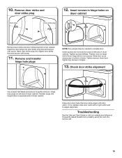
... reinstall door. Tighten screws halfway. Close door and check that door strike aligns with screw. Insert screws in hinge holes on opposite side of dryer cabinet. Insert door strike plug into the bottom holes on left side of a service call. 19 Remove and transfer hinge hole plugs NOTE: ...Two people may be needed , slide door catch left side of dryer cabinet. If it is over screws. Troubleshooting See the Use and Care Guide or visit our website and reference Frequently Asked Questions to adjust ...
... reinstall door. Tighten screws halfway. Close door and check that door strike aligns with screw. Insert screws in hinge holes on opposite side of dryer cabinet. Insert door strike plug into the bottom holes on left side of a service call. 19 Remove and transfer hinge hole plugs NOTE: ...Two people may be needed , slide door catch left side of dryer cabinet. If it is over screws. Troubleshooting See the Use and Care Guide or visit our website and reference Frequently Asked Questions to adjust ...
Owners Manual
Page 2
DRYER SAFETY IMPORTANT: The gas installation must be electrically grounded in accordance with local codes, or in the absence of local codes, with the National Fuel Gas Code, ANSI Z223.1/NFPA 54, or the Natural Gas and Propane Installation Code, CSA B149.1. The dryer must conform with local codes, or in the absence of local codes, with the National Electrical Code, ANSI/NFPA 70, or the Canadian Electrical Code, Part 1, CSA C22.1. 2
DRYER SAFETY IMPORTANT: The gas installation must be electrically grounded in accordance with local codes, or in the absence of local codes, with the National Fuel Gas Code, ANSI Z223.1/NFPA 54, or the Natural Gas and Propane Installation Code, CSA B149.1. The dryer must conform with local codes, or in the absence of local codes, with the National Electrical Code, ANSI/NFPA 70, or the Canadian Electrical Code, Part 1, CSA C22.1. 2
Owners Manual
Page 4
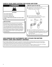
... using the drying rack. 4 See Installation Instructions. each load. ■ Replace plastic or foil vent material with heat, dryers require good air flow to the dryer plays a big role in the load. During Sensor Dry/Automatic Dry cycles, drying air temperature or moisture level is complete,...mm) diameter heavy, rigid vent material. Blocked or crushed vents as well as improper venting installation will reduce your drying times and improve your dryer for the occasional damp load that needs a little more than four 90° elbows in shrinkage, wrinkling, and static due to over-drying...
... using the drying rack. 4 See Installation Instructions. each load. ■ Replace plastic or foil vent material with heat, dryers require good air flow to the dryer plays a big role in the load. During Sensor Dry/Automatic Dry cycles, drying air temperature or moisture level is complete,...mm) diameter heavy, rigid vent material. Blocked or crushed vents as well as improper venting installation will reduce your drying times and improve your dryer for the occasional damp load that needs a little more than four 90° elbows in shrinkage, wrinkling, and static due to over-drying...
Owners Manual
Page 5
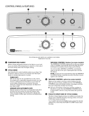
... starts at the end of a cycle. WRINKLE CONTROL Feature (on the control. On some models) The WRINKLE CONTROL feature will run the dryer for detailed descriptions of cycles. The WRINKLE CONTROL option periodically tumbles, rearranges, and fluffs the load to help avoid wrinkling. Turn the WRINKLE CONTROL...drying cycle is also selected. 3 WRINKLE CONTROL option (on your load. It periodically starts and stops the dryer, tumbling the load without heat to help keep wrinkles from the dryer as soon as it stops, wrinkles can form. at the end of the cycle reduces wrinkling. Turn the...
... starts at the end of a cycle. WRINKLE CONTROL Feature (on the control. On some models) The WRINKLE CONTROL feature will run the dryer for detailed descriptions of cycles. The WRINKLE CONTROL option periodically tumbles, rearranges, and fluffs the load to help avoid wrinkling. Turn the WRINKLE CONTROL...drying cycle is also selected. 3 WRINKLE CONTROL option (on your load. It periodically starts and stops the dryer, tumbling the load without heat to help keep wrinkles from the dryer as soon as it stops, wrinkles can form. at the end of the cycle reduces wrinkling. Turn the...


