Use and Care Guide
Page 2
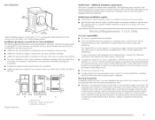
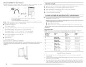
...Options ... 26 End of Cycle Signal ...26 Changing Cycles, Modifiers and Options 27 Drying Rack Option ...27 DRYER CARE... 28 Cleaning the Dryer Location 28 Cleaning the I.int Screen ...28 Cleaning the Dryer Interior 29 Removing Accumulated I 'ampoule d'6clairage du tambour 58 DI_PANNAGE ... 59...iiiiiiiiiiiiiiiiiiiiiiiiiiiOnly 5 Electrical Requirements - TABLE OF CONTENTS DRYER SAFETY... 3 INSTALLATION INSTRUCTIONS 4 Tools and Parts... 4 l.ocation Requirements ...4 Electrical Requirements - U.S.A. Canada Only 7 Electrical Connection - U.S.A. Pour le Canada seulement...
...Options ... 26 End of Cycle Signal ...26 Changing Cycles, Modifiers and Options 27 Drying Rack Option ...27 DRYER CARE... 28 Cleaning the Dryer Location 28 Cleaning the I.int Screen ...28 Cleaning the Dryer Interior 29 Removing Accumulated I 'ampoule d'6clairage du tambour 58 DI_PANNAGE ... 59...iiiiiiiiiiiiiiiiiiiiiiiiiiiOnly 5 Electrical Requirements - TABLE OF CONTENTS DRYER SAFETY... 3 INSTALLATION INSTRUCTIONS 4 Tools and Parts... 4 l.ocation Requirements ...4 Electrical Requirements - U.S.A. Canada Only 7 Electrical Connection - U.S.A. Pour le Canada seulement...
Use and Care Guide
Page 3
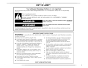
...'t immediately follow basic precautions, including the following: [] Read all safety messages. IMPORTANT SAFETY iNSTRUCTiONS WARNING: To reduce the risk of fire, electric shock, or injury to persons when using the dryer. [] Do not place items exposed to reduce the chance of injury, and tell you and others are not followed. i_i_!iii_i_iiIi...
...'t immediately follow basic precautions, including the following: [] Read all safety messages. IMPORTANT SAFETY iNSTRUCTiONS WARNING: To reduce the risk of fire, electric shock, or injury to persons when using the dryer. [] Do not place items exposed to reduce the chance of injury, and tell you and others are not followed. i_i_!iii_i_iiIi...
Use and Care Guide
Page 4
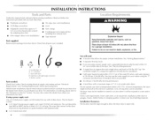
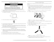
...explosion, or fire. See "Electrical Requirements." • A sturdy floor to support the total weight (dryer and load) of the dryer. You may also contact the dealer from dryer drum. Do not operate your washer using a power supply cord, a grounded electrical outlet located within 4 ft (1.2...Requirements." • A separate 30-amp circuit. • [f you purchased your local building inspector. At lower temperatures, the dryer might not shut off at least 18 inches (46 cm) above the floor for best performance. • A level floor with right-angle connector E. Gather the required ...
...explosion, or fire. See "Electrical Requirements." • A sturdy floor to support the total weight (dryer and load) of the dryer. You may also contact the dealer from dryer drum. Do not operate your washer using a power supply cord, a grounded electrical outlet located within 4 ft (1.2...Requirements." • A separate 30-amp circuit. • [f you purchased your local building inspector. At lower temperatures, the dryer might not shut off at least 18 inches (46 cm) above the floor for best performance. • A level floor with right-angle connector E. Gather the required ...
Use and Care Guide
Page 5
...using and follow the instructions provided for this dryer. A time-delay fuse or circuit breaker is permanently connected to the neutral conductor (white wire) within the dryer. If the dryer is installed with the National Electrical Code, ANSI/NFPA 70-latest edition and all...(center or white wire) of installation and servicing. • Additional clearances might be removed from the neutral conductor. .... 5 Dryer Dimensions Mobile home - Electrical Connection [b properly install your dealer. • Special provisions must be required for wall, door and floor moldings. • ...
...using and follow the instructions provided for this dryer. A time-delay fuse or circuit breaker is permanently connected to the neutral conductor (white wire) within the dryer. If the dryer is installed with the National Electrical Code, ANSI/NFPA 70-latest edition and all...(center or white wire) of installation and servicing. • Additional clearances might be removed from the neutral conductor. .... 5 Dryer Dimensions Mobile home - Electrical Connection [b properly install your dealer. • Special provisions must be required for wall, door and floor moldings. • ...
Use and Care Guide
Page 6
...connecting by a white cover. terminal or lead on the power supply cord: if it will reduce the risk of electric shock by a qualified electrician. This dryer uses a cord having an equipment-grounding conductor and a grounding plug. Check with ring or spade terminals and UI.... The 3-wire power supply cord, at least 4 ft (1.22 m) long, must be either green or [)are in "Electrical Connection - U.S.A. listed strain relief....
...connecting by a white cover. terminal or lead on the power supply cord: if it will reduce the risk of electric shock by a qualified electrician. This dryer uses a cord having an equipment-grounding conductor and a grounding plug. Check with ring or spade terminals and UI.... The 3-wire power supply cord, at least 4 ft (1.22 m) long, must be either green or [)are in "Electrical Connection - U.S.A. listed strain relief....
Use and Care Guide
Page 7
... plug provided with all local codes. For further information, please reference the service numbers located in death or electrical shock. Failure to whether the dryer is equipped with a qualified electrician or service representative or personnel if you are using a replacement power supply... can result in conformance with a CSA International Certified Power Cord intended to an individual branch circuit This dryer is recommended. .... _ •_ 51 Electrical Shock Hazard Plug into a standard 14-30R wall receptacle. A time-delay fuse or circuit breaker is equipped...
... plug provided with all local codes. For further information, please reference the service numbers located in death or electrical shock. Failure to whether the dryer is equipped with a qualified electrician or service representative or personnel if you are using a replacement power supply... can result in conformance with a CSA International Certified Power Cord intended to an individual branch circuit This dryer is recommended. .... _ •_ 51 Electrical Shock Hazard Plug into a standard 14-30R wall receptacle. A time-delay fuse or circuit breaker is equipped...
Use and Care Guide
Page 9
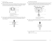
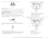
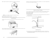
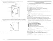
Put the tabs of the two clamp sections into the hole below terminal block opening . Put the threaded section of electrical connection: .... 9 Strain relief tab pointing down , and hold the two clamp sections togethen Style 2: Direct wire strain relief Unscrew the... removable conduit connector and any screws from a 3/4" (1.9 cm) UI. The strain relief should have a tight fit with the dryer cabinet and be in a horizontal position. Tighten strain relief screw against the direct wire cable. Tighten strain relief screws just enough to hold in a...
Put the tabs of the two clamp sections into the hole below terminal block opening . Put the threaded section of electrical connection: .... 9 Strain relief tab pointing down , and hold the two clamp sections togethen Style 2: Direct wire strain relief Unscrew the... removable conduit connector and any screws from a 3/4" (1.9 cm) UI. The strain relief should have a tight fit with the dryer cabinet and be in a horizontal position. Tighten strain relief screw against the direct wire cable. Tighten strain relief screws just enough to hold in a...

Use and Care Guide
Page 10
...'nter silver-colored te'rminal block screw D. Spade tenTfinals with upturned end_ L ?_" ( 1.9 cm) U_ li_ted strain relief C. Neutral ground wire C. Electrical Connection Options If your home has: 4-wire receptacle (NEMA type 14-30R) __._._ 4-wire direct (12.7 cm) 3-wire receptacle (NEMA type 10-...conductor scren,v B. Center silver-colored terminal block scr_w L Ne_utral wire (white or center wire) listed, 120/240-volt minimum, 30-amp, dryer power supply cord* 3-wire connection: Power Supply Cord A fused disconnect or circuit breaker box* 3-wire connection: Direct Wire *If local codes...
...'nter silver-colored te'rminal block screw D. Spade tenTfinals with upturned end_ L ?_" ( 1.9 cm) U_ li_ted strain relief C. Neutral ground wire C. Electrical Connection Options If your home has: 4-wire receptacle (NEMA type 14-30R) __._._ 4-wire direct (12.7 cm) 3-wire receptacle (NEMA type 10-...conductor scren,v B. Center silver-colored terminal block scr_w L Ne_utral wire (white or center wire) listed, 120/240-volt minimum, 30-amp, dryer power supply cord* 3-wire connection: Power Supply Cord A fused disconnect or circuit breaker box* 3-wire connection: Direct Wire *If local codes...
Use and Care Guide
Page 11
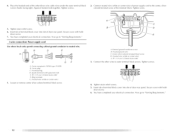
... relief screws. 6. Secure cover with hold- Direct wire cable must have completed your electrical connection. Strip insulation back 1" (2.5 cm). C. Tighten screw. Lxternal ground conductor screw B. Shape ends of extra length so dryer can be moved if needed. Dotted line shows position of the terminal block. Y4"...the terminal block (hook facing right), squeeze hooked end together and tighten screw, as shown. Tighten screw. Ground wire (green or bare) of dryer rear panel. Insert tab of terminal block cover into a hook shape. You have 5 ft (1.52 m) of wires into slot of power ...
... relief screws. 6. Secure cover with hold- Direct wire cable must have completed your electrical connection. Strip insulation back 1" (2.5 cm). C. Tighten screw. Lxternal ground conductor screw B. Shape ends of extra length so dryer can be moved if needed. Dotted line shows position of the terminal block. Y4"...the terminal block (hook facing right), squeeze hooked end together and tighten screw, as shown. Tighten screw. Ground wire (green or bare) of dryer rear panel. Insert tab of terminal block cover into a hook shape. You have 5 ft (1.52 m) of wires into slot of power ...
Use and Care Guide
Page 12
...receptacle (NEMA type IO-30R) B. 3-wire plug C. Tighten strain relief screws. 5. Tighten screws, !! !! 2. Tighten screw. 5. You have completed your electrical connection. Ring term[nab G. Center silver-colored terminal block screw D. Now go to "Venting Requirements." 3-wire connection: Power supply cord Use where local codes... or center wire) of the terminal block. Tighten strain relief screw. 6. A. Insert tab of terminal block cover into slot of dryer rear panel. Neutral wire (white or center wire) E. _" t 1.9 cm) U_ listed strain relief 3, Connect the other direct...
...receptacle (NEMA type IO-30R) B. 3-wire plug C. Tighten strain relief screws. 5. Tighten screws, !! !! 2. Tighten screw. 5. You have completed your electrical connection. Ring term[nab G. Center silver-colored terminal block screw D. Now go to "Venting Requirements." 3-wire connection: Power supply cord Use where local codes... or center wire) of the terminal block. Tighten strain relief screw. 6. A. Insert tab of terminal block cover into slot of dryer rear panel. Neutral wire (white or center wire) E. _" t 1.9 cm) U_ listed strain relief 3, Connect the other direct...
Use and Care Guide
Page 13
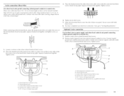
...Wire Use where local codes permit connecting cabinet-ground conductor to "Venting Requirements." Remove neutral ground wire from end of extra length so dryer can be moved if needed. Tighten screw. 1, koosen or remove center silver-colored terminal block screw. 2. Neutral ground wire' ...wires under time outer terminal screws (hooks facing right). t" _B.9 co) When connecting the terminal shown. Direct wire cable must have completed your electrical connection. down screw. 6. Neutral wire (white" or center wire') E. _" (1.9 cm) UL list_'d strain r_qi_f A. block to neutral wire....
...Wire Use where local codes permit connecting cabinet-ground conductor to "Venting Requirements." Remove neutral ground wire from end of extra length so dryer can be moved if needed. Tighten screw. 1, koosen or remove center silver-colored terminal block screw. 2. Neutral ground wire' ...wires under time outer terminal screws (hooks facing right). t" _B.9 co) When connecting the terminal shown. Direct wire cable must have completed your electrical connection. down screw. 6. Neutral wire (white" or center wire') E. _" (1.9 cm) UL list_'d strain r_qi_f A. block to neutral wire....
Use and Care Guide
Page 14
...may result in reduced airflow and poor performance. • Do not install flexible metal vent in death WARNING: Io reduce the risk of dryer rear panel. Fire Hazard Use a heavy metal vent. Failure to outer terminal block screws. can be used. 4. Better 14 3. Do ...gas vent, chimney, wall, ceiling or a concealed space of a building. Connect a separate copper ground wire from your dealer or by calling Maytag Services. Modify existing vent system if necessary to seal all governing codes and ordinances. Tighten strain relief screws. 5. Elbows 45 ° elbows ...
...may result in reduced airflow and poor performance. • Do not install flexible metal vent in death WARNING: Io reduce the risk of dryer rear panel. Fire Hazard Use a heavy metal vent. Failure to outer terminal block screws. can be used. 4. Better 14 3. Do ...gas vent, chimney, wall, ceiling or a concealed space of a building. Connect a separate copper ground wire from your dealer or by calling Maytag Services. Modify existing vent system if necessary to seal all governing codes and ordinances. Tighten strain relief screws. 5. Elbows 45 ° elbows ...

Use and Care Guide
Page 15
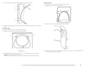
...fle'xible metal vent G. onotuseductape. B D - Fxhaust hood E. Choose your exhaust installation type Recommended exhaust installations [ypical installations vent the dryer from the rear of the exhaust {such as flowers, rocks or bushes, snow line, etc.). Box hood style The angled hood style ...{shown here) is acceptable. 4" (10.2 cm)_ A-- IIII J ll B A. Exhaust hood must be in the path of the dryer. V_'nt letlgth necessary to connect elbows H. _xhaust outlet Standard exhaust installation with a magnetic latch. B i (10.2 cm) A. improper venting can...
...fle'xible metal vent G. onotuseductape. B D - Fxhaust hood E. Choose your exhaust installation type Recommended exhaust installations [ypical installations vent the dryer from the rear of the exhaust {such as flowers, rocks or bushes, snow line, etc.). Box hood style The angled hood style ...{shown here) is acceptable. 4" (10.2 cm)_ A-- IIII J ll B A. Exhaust hood must be in the path of the dryer. V_'nt letlgth necessary to connect elbows H. _xhaust outlet Standard exhaust installation with a magnetic latch. B i (10.2 cm) A. improper venting can...
Use and Care Guide
Page 16
... 54 ft (16.5 m) Flexible metal 31 ft (9.4 m) ... 2 Rigid metal 44 ft (13.4 m) Flexible metal 27 ft (8.2 m) ... 3 Rigid metal 35 ft (10.7 m) Flexible metal 25 ft 17.6 m) ... 4 Rigid metal 27 ft (8.2 m) Flexible metal 23 ft (7 m) 58 ft (17.7 m) 28 ft/8.5 m) 48 ft (14.6 m)...possible. Install exhaust hood. Alternate installations for close - clearance installations are available for your installation. Over-the-top installation (also available" with dryer vent to wall vent mismatch): Part Number 43960"¢7 - 0" (0 cm) to 18" (45.72 cm) mismatch Part Number 4396011 -...
... 54 ft (16.5 m) Flexible metal 31 ft (9.4 m) ... 2 Rigid metal 44 ft (13.4 m) Flexible metal 27 ft (8.2 m) ... 3 Rigid metal 35 ft (10.7 m) Flexible metal 25 ft 17.6 m) ... 4 Rigid metal 27 ft (8.2 m) Flexible metal 23 ft (7 m) 58 ft (17.7 m) 28 ft/8.5 m) 48 ft (14.6 m)...possible. Install exhaust hood. Alternate installations for close - clearance installations are available for your installation. Over-the-top installation (also available" with dryer vent to wall vent mismatch): Part Number 43960"¢7 - 0" (0 cm) to 18" (45.72 cm) mismatch Part Number 4396011 -...
Use and Care Guide
Page 17
...a 4 _ (10.2 cm) clamp, connect vent to finish turning the legs until it is clean. A. Place cardboard under each of the dryer (not the top or console panel). Remove old rubber washer from the dryer carton. Use a wrench to exhaust outlet in the flexible gas line. 4. NOTE: Do not overtighten. Attach... water faucet using the new inlet hoses. Gently lay the dryer on coupling by hand. Continue with new rubber washer provided. leave enough room to cold water faucet. Attach straight end of small hose. The dryer vent must be attached directly to cold water faucet, go ...
...a 4 _ (10.2 cm) clamp, connect vent to finish turning the legs until it is clean. A. Place cardboard under each of the dryer (not the top or console panel). Remove old rubber washer from the dryer carton. Use a wrench to exhaust outlet in the flexible gas line. 4. NOTE: Do not overtighten. Attach... water faucet using the new inlet hoses. Gently lay the dryer on coupling by hand. Continue with new rubber washer provided. leave enough room to cold water faucet. Attach straight end of small hose. The dryer vent must be attached directly to cold water faucet, go ...
Use and Care Guide
Page 18
...of the 2 hinges that the water faucets are on the side of the dryer between the top of the dryer and the dryer cabinet, check the levelness from each of the dryer or work space to the front panel of the dryer by placing a level in Step 2. NOIE: Do not overtighten. Remove" ... 12. A 'B ]hen, by first placing a level on a flat, protected surface, with an additional two-thirds turn. 10. Damage to back. Check that attach the dryer door to protect the surface. A. _oose'll the'se' 5creq,vs. _. Use a wrench to a left-side opening, if desired. 1. Check for levelness. You can...
...of the 2 hinges that the water faucets are on the side of the dryer between the top of the dryer and the dryer cabinet, check the levelness from each of the dryer or work space to the front panel of the dryer by placing a level in Step 2. NOIE: Do not overtighten. Remove" ... 12. A 'B ]hen, by first placing a level on a flat, protected surface, with an additional two-thirds turn. 10. Damage to back. Check that attach the dryer door to protect the surface. A. _oose'll the'se' 5creq,vs. _. Use a wrench to a left-side opening, if desired. 1. Check for levelness. You can...
Use and Care Guide
Page 19
... where the hinges were removed in the same holes. _ " _" 6. Door strike B. Remove the door strike from the dryer door. 2. Cbsmetic screw Reinstall the door strike and cosmetic screw on the same side of the door. Remove the cosmetic screw opposite the door strike. 3. I A.... from where they were removed. I ..a Install tile 2 hinges to the front panel. NOTE: Door strike and plugs must be on the opposite side of the dryer using 4 screws. Replace the 4 screws in Step 4. Reverse the strike 1. Reinstall the door 1. Use tile non-slotted side to attach the hinge to the ...
... where the hinges were removed in the same holes. _ " _" 6. Door strike B. Remove the door strike from the dryer door. 2. Cbsmetic screw Reinstall the door strike and cosmetic screw on the same side of the door. Remove the cosmetic screw opposite the door strike. 3. I A.... from where they were removed. I ..a Install tile 2 hinges to the front panel. NOTE: Door strike and plugs must be on the opposite side of the dryer using 4 screws. Replace the 4 screws in Step 4. Reverse the strike 1. Reinstall the door 1. Use tile non-slotted side to attach the hinge to the ...
Use and Care Guide
Page 20
... bottom screw holes in the door. Check for certain [)art replacement or repair. 13. ]i_st dryer operation by placing screw heads into an outlet and/or electrical supply is an extra part, go away. 20 Check the dryer's final location. NOTE: Glass door models have a protective film on the window that you live...
... bottom screw holes in the door. Check for certain [)art replacement or repair. 13. ]i_st dryer operation by placing screw heads into an outlet and/or electrical supply is an extra part, go away. 20 Check the dryer's final location. NOTE: Glass door models have a protective film on the window that you live...
Use and Care Guide
Page 21
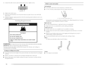
...reduce the risk of oil on it (including cooking oils). Turn the knob to persons, read the IMPORTANT SAFETY INSTRUCTIONS before each load. Your dryer may not have all of this appliance. Clean lint screen before operating this manual for Sensor [Dry, Timed or Steam Cycles will show in ...can result in death, explosion, or fire. Press POWER. 4. Fire Hazard No washer can result in death or tire. Do not dry anything that has ever had anything that has ever had any type of fire, electric shock, or injury to the selected cycle. [-he preset settings for more detailed ...
...reduce the risk of oil on it (including cooking oils). Turn the knob to persons, read the IMPORTANT SAFETY INSTRUCTIONS before each load. Your dryer may not have all of this appliance. Clean lint screen before operating this manual for Sensor [Dry, Timed or Steam Cycles will show in ...can result in death, explosion, or fire. Press POWER. 4. Fire Hazard No washer can result in death or tire. Do not dry anything that has ever had anything that has ever had any type of fire, electric shock, or injury to the selected cycle. [-he preset settings for more detailed ...
Use and Care Guide
Page 22
.... 5. (OPTIONAL STEP) If desired, select OPTIONS. Once a dryness level is displayed. For more details, see "End of selecting the cycle, the dryer automatically shuts off. • If you want the load. Press START. To use a Sensor Dry Cycle Press TEMP until the desired drying time is ... only with Timed Cycles and the Custom Refresh cycle. How the Sensi-Care TM Drying System Works Moisture-sensing strips and ternperature sensors inside the dryer drum monitor how fast the load is closed. • Press PAUSE/CANCEl_ • Adjust Dryness. • MORE • NORMAL • L_SS ...
.... 5. (OPTIONAL STEP) If desired, select OPTIONS. Once a dryness level is displayed. For more details, see "End of selecting the cycle, the dryer automatically shuts off. • If you want the load. Press START. To use a Sensor Dry Cycle Press TEMP until the desired drying time is ... only with Timed Cycles and the Custom Refresh cycle. How the Sensi-Care TM Drying System Works Moisture-sensing strips and ternperature sensors inside the dryer drum monitor how fast the load is closed. • Press PAUSE/CANCEl_ • Adjust Dryness. • MORE • NORMAL • L_SS ...


