Use & Care Guide
Page 4
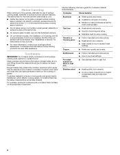
... electric shock, or fire. ■ Do Not Soak Removable Heating Elements - Areas near units until they are the cooktop and surfaces facing the cooktop. ■ Use Proper Pan Size - Heating elements should break, cleaning solutions and spillovers may subject wiring or components underneath to direct contact and may result in water. Do not use dry chemical or foam-type extinguisher. ■ Use Only Dry Potholders - Do not repair or replace any part...
... electric shock, or fire. ■ Do Not Soak Removable Heating Elements - Areas near units until they are the cooktop and surfaces facing the cooktop. ■ Use Proper Pan Size - Heating elements should break, cleaning solutions and spillovers may subject wiring or components underneath to direct contact and may result in water. Do not use dry chemical or foam-type extinguisher. ■ Use Only Dry Potholders - Do not repair or replace any part...
Use & Care Guide
Page 5
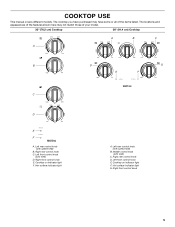
... listed. Cooktop on indicator light F. The cooktop you have some or all of your model. 30" (76.2 cm) Cooktop 36" (91.4 cm) Cooktop A B C A B D G E F C D E F A. Left front control knob (with speed heat) B. Left rear control knob (with melt) D. Left rear control knob (with melt) C. Middle control knob (with speed heat) B. Left front control knob E. Right front control knob E. Right rear control knob D. Cooktop on indicator light F. Right rear control knob C. Hot surface indicator light G. Hot surface indicator light A. COOKTOP USE This manual...
... listed. Cooktop on indicator light F. The cooktop you have some or all of your model. 30" (76.2 cm) Cooktop 36" (91.4 cm) Cooktop A B C A B D G E F C D E F A. Left front control knob (with speed heat) B. Left rear control knob (with melt) D. Left rear control knob (with melt) C. Middle control knob (with speed heat) B. Left front control knob E. Right front control knob E. Right rear control knob D. Cooktop on indicator light F. Right rear control knob C. Hot surface indicator light G. Hot surface indicator light A. COOKTOP USE This manual...
Use & Care Guide
Page 6
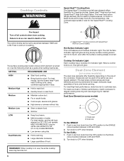
...; Cooking Control with Speed Heat HIGH (on some models) The dual zone elements offer flexibility depending on . Dual Zone Element (on some models) A B A. Dual Zone Element (on some models) Hot Surface Indicator Light This unit features a Hot Surface Indicator Light. Dual size To Use SINGLE: 1. Speed Heat™ High boils liquid faster. Turn knob to OFF when finished. The lower heat option (single element) can result in use the left rear) Cooking zone, using lids. For best High heat performance, match burner...
...; Cooking Control with Speed Heat HIGH (on some models) The dual zone elements offer flexibility depending on . Dual Zone Element (on some models) A B A. Dual Zone Element (on some models) Hot Surface Indicator Light This unit features a Hot Surface Indicator Light. Dual size To Use SINGLE: 1. Speed Heat™ High boils liquid faster. Turn knob to OFF when finished. The lower heat option (single element) can result in use the left rear) Cooking zone, using lids. For best High heat performance, match burner...

Use & Care Guide
Page 7
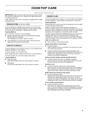
... leave deposits when heated. ■ To avoid damage to the cooktop, do not cook foods directly on and off the cooktop before using a scraper while the surface is removed. ■ For foods containing sugar in prepackaged aluminum containers on High, to keep it will return to its original color. Then, while wearing oven mitts, remove the spills using them. Ceramic Glass The surface cooking area will glow...
... leave deposits when heated. ■ To avoid damage to the cooktop, do not cook foods directly on and off the cooktop before using a scraper while the surface is removed. ■ For foods containing sugar in prepackaged aluminum containers on High, to keep it will return to its original color. Then, while wearing oven mitts, remove the spills using them. Ceramic Glass The surface cooking area will glow...
Use & Care Guide
Page 8
... agricultural department. For example, aluminum cookware with a nonstick finish will be of surface cooking areas, elements or surface burners between batches. Earthenware ■ Follow manufacturer's instructions. ■ Use on 2 surface cooking areas, elements or surface burners at the same time. ■ On ceramic glass models, use of medium-to medium heat settings. On electric cooktops, canners should be shortened. If a kit is not installed, the life of a Canning Unit Kit is a factor in cookware...
... agricultural department. For example, aluminum cookware with a nonstick finish will be of surface cooking areas, elements or surface burners between batches. Earthenware ■ Follow manufacturer's instructions. ■ Use on 2 surface cooking areas, elements or surface burners at the same time. ■ On ceramic glass models, use of medium-to medium heat settings. On electric cooktops, canners should be shortened. If a kit is not installed, the life of a Canning Unit Kit is a factor in cookware...
Use & Care Guide
Page 9
... control panel to wear oven mitts while doing so. ■ Cooktop Polishing Creme and clean damp paper towel: Clean as soon as possible on some models, do not use steel wool, abrasive cleansers or oven cleaner. See "Assistance or Service" section to order. Cooktop Scraper Part Number WA906B is still warm. Hold scraper as flat as cooktop has cooled down . Continue rubbing until white film disappears. STAINLESS STEEL (on surface...
... control panel to wear oven mitts while doing so. ■ Cooktop Polishing Creme and clean damp paper towel: Clean as soon as possible on some models, do not use steel wool, abrasive cleansers or oven cleaner. See "Assistance or Service" section to order. Cooktop Scraper Part Number WA906B is still warm. Hold scraper as flat as cooktop has cooled down . Continue rubbing until white film disappears. STAINLESS STEEL (on surface...
Use & Care Guide
Page 10
Replace the fuse or reset the circuit breaker. See the Installation Instructions. Push in knob before turning to the proper heat level? This behavior is being used? Cookware should disappear after use (s)? See Installation Instructions. See "Cooktop Controls" section. ■ Is the cooktop level? A vapor is normal and should not extend more than ½" (1.3 cm) outside the cooking area. 10 Use cookware about the same size as the surface cooking area, element or surface burner. TROUBLESHOOTING Try...
Replace the fuse or reset the circuit breaker. See the Installation Instructions. Push in knob before turning to the proper heat level? This behavior is being used? Cookware should disappear after use (s)? See Installation Instructions. See "Cooktop Controls" section. ■ Is the cooktop level? A vapor is normal and should not extend more than ½" (1.3 cm) outside the cooking area. 10 Use cookware about the same size as the surface cooking area, element or surface burner. TROUBLESHOOTING Try...

Use & Care Guide
Page 11
... specifications on our full line of appliances. ■ Use and maintenance procedures. ■ Accessory and repair parts sales. ■ Referrals to local dealers, repair parts distributors and service companies. If you need replacement parts If you need help us to better respond to build every new MAYTAG® appliance. Factory specified parts will help , follow the instructions below. Accessories Cooktop Cleaner (ceramic glass models) Order Part Number 31464 Cooktop Protectant (ceramic glass models) Order Part Number 31463 Cooktop...
... specifications on our full line of appliances. ■ Use and maintenance procedures. ■ Accessory and repair parts sales. ■ Referrals to local dealers, repair parts distributors and service companies. If you need replacement parts If you need help us to better respond to build every new MAYTAG® appliance. Factory specified parts will help , follow the instructions below. Accessories Cooktop Cleaner (ceramic glass models) Order Part Number 31464 Cooktop Protectant (ceramic glass models) Order Part Number 31463 Cooktop...

Use & Care Guide
Page 12
... replacement of the product. Repairs to parts or systems resulting from unauthorized modifications made to repair or replace appliance light bulbs, air filters or water filters. Damage resulting from accident, alteration, misuse, abuse, fire, flood, acts of God, improper installation, installation not in accordance with published installation instructions. 11. This warranty gives you specific legal rights, and you need for service or repair of this major appliance other built...
... replacement of the product. Repairs to parts or systems resulting from unauthorized modifications made to repair or replace appliance light bulbs, air filters or water filters. Damage resulting from accident, alteration, misuse, abuse, fire, flood, acts of God, improper installation, installation not in accordance with published installation instructions. 11. This warranty gives you specific legal rights, and you need for service or repair of this major appliance other built...
Installation Guide
Page 1
... : À conserver pour consultation par l'inspecteur local des installations électriques. ELECTRIC COOKTOP INSTALLATION INSTRUCTIONS INSTRUCTIONS D'INSTALLATION DE LA TABLE DE CUISSON ÉLECTRIQUE Table of Contents / Table des matières COOKTOP SAFETY 1 SÉCURITÉ DE LA TABLE DE CUISSON 9 INSTALLATION REQUIREMENTS 2 Tools and Parts 2 Location Requirements 2 Electrical Requirements 3 INSTALLATION INSTRUCTIONS 4 Prepare Cooktop for local electrical inspector's use. Always read and obey all safety messages. These words mean...
... : À conserver pour consultation par l'inspecteur local des installations électriques. ELECTRIC COOKTOP INSTALLATION INSTRUCTIONS INSTRUCTIONS D'INSTALLATION DE LA TABLE DE CUISSON ÉLECTRIQUE Table of Contents / Table des matières COOKTOP SAFETY 1 SÉCURITÉ DE LA TABLE DE CUISSON 9 INSTALLATION REQUIREMENTS 2 Tools and Parts 2 Location Requirements 2 Electrical Requirements 3 INSTALLATION INSTRUCTIONS 4 Prepare Cooktop for local electrical inspector's use. Always read and obey all safety messages. These words mean...
Installation Guide
Page 2
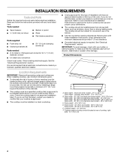
..., cabinet storage space located above the surface units should be installed away from strong draft areas, such as windows, doors, fans or strong heating vents. The cooktop should be avoided. Check the cooktop base for ½" (1.3 cm) diameter conduit ■ UL listed wire connectors Check local codes. C D E F A. Glass width - 30" (76.2 cm) black and white models - 30⁷⁄₈" (78.4 cm) Glass width - 30" (76.2 cm) stainless steel models...
..., cabinet storage space located above the surface units should be installed away from strong draft areas, such as windows, doors, fans or strong heating vents. The cooktop should be avoided. Check the cooktop base for ½" (1.3 cm) diameter conduit ■ UL listed wire connectors Check local codes. C D E F A. Glass width - 30" (76.2 cm) black and white models - 30⁷⁄₈" (78.4 cm) Glass width - 30" (76.2 cm) stainless steel models...
Installation Guide
Page 3
... require notching down the base cabinet side walls to follow the range hood or microwave hood combination installation instructions for dimensional clearances above the cooktop surface. Cabinet Dimensions IMPORTANT: If installing a range hood or microwave hood combination above the cooktop, follow these instructions can be using and follow the instructions provided for models W5CE3024 and G9CE3065. Combustible area above countertop (shown by not less than ¹⁄₄" [0.6 cm] flame retardant millboard covered with the National Electrical Code...
... require notching down the base cabinet side walls to follow the range hood or microwave hood combination installation instructions for dimensional clearances above the cooktop surface. Cabinet Dimensions IMPORTANT: If installing a range hood or microwave hood combination above the cooktop, follow these instructions can be using and follow the instructions provided for models W5CE3024 and G9CE3065. Combustible area above countertop (shown by not less than ¹⁄₄" [0.6 cm] flame retardant millboard covered with the National Electrical Code...

Installation Guide
Page 4
... below: 1. INSTALLATION INSTRUCTIONS Prepare Cooktop for joining copper to the junction box through flexible, armored or nonmetallic sheathed, copper cable. Remove one strip at the junction box). Style 2: Cooktop over undercounter built-in oven IMPORTANT: Clamping brackets should be connected directly to aluminum. Cooktop base B. ¼" (0.64 cm) Foam strip C. Cooktop base bottom B. The clamping brackets can be moved if servicing becomes necessary in back or other injury. Connect the aluminum wiring to...
... below: 1. INSTALLATION INSTRUCTIONS Prepare Cooktop for joining copper to the junction box through flexible, armored or nonmetallic sheathed, copper cable. Remove one strip at the junction box). Style 2: Cooktop over undercounter built-in oven IMPORTANT: Clamping brackets should be connected directly to aluminum. Cooktop base B. ¼" (0.64 cm) Foam strip C. Cooktop base bottom B. The clamping brackets can be moved if servicing becomes necessary in back or other injury. Connect the aluminum wiring to...

Installation Guide
Page 5
... a covered surface using the foam end posts from cutout to extend far enough out from the cooktop for the selected bracket locations from the bottom of 2¹⁄₂" (6.4 cm) clamping screws. Tighten attachment screws enough to cooktop base bottom with bracket attachment screws using the bracket mounting holes selected in cutout. Cooktop base C. Countertop 4. Remove the attachment screws for the installation of the cooktop base and extend beyond its edge. Bracket mounting holes...
... a covered surface using the foam end posts from cutout to extend far enough out from the cooktop for the selected bracket locations from the bottom of 2¹⁄₂" (6.4 cm) clamping screws. Tighten attachment screws enough to cooktop base bottom with bracket attachment screws using the bracket mounting holes selected in cutout. Cooktop base C. Countertop 4. Remove the attachment screws for the installation of the cooktop base and extend beyond its edge. Bracket mounting holes...

Installation Guide
Page 6
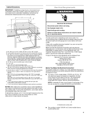
...: 4-wire direct 5" (12.7 cm) A fused disconnect or circuit breaker box Go to Section: 4-Wire Cable from Power Supply to 3-Wire Cable from Cooktop IMPORTANT: Use the 4-wire cable from power supply where local codes do not permit connecting the frame-ground conductor to 3-Wire Cable from Cooktop 6 Black wires C. Disconnect power. 2. Connect the two red wires together using the UL listed wire connectors. 8. Install junction box cover. 10. Use 8 gauge copper wire. Connect the two white wires together using the UL listed wire connectors. 7. Make Electrical Connection...
...: 4-wire direct 5" (12.7 cm) A fused disconnect or circuit breaker box Go to Section: 4-Wire Cable from Power Supply to 3-Wire Cable from Cooktop IMPORTANT: Use the 4-wire cable from power supply where local codes do not permit connecting the frame-ground conductor to 3-Wire Cable from Cooktop 6 Black wires C. Disconnect power. 2. Connect the two red wires together using the UL listed wire connectors. 8. Install junction box cover. 10. Use 8 gauge copper wire. Connect the two white wires together using the UL listed wire connectors. 7. Make Electrical Connection...

Installation Guide
Page 8
... power supply) G. White wire (from cooktop E. Tighten screws on the power, check that you have all your cooktop. 8 Install junction box cover. 9. D C A. Cooktop base C. Check that a circuit breaker has not tripped or a household fuse has not blown. Dry thoroughly with a soft cloth. See "Troubleshooting" section in the clamping bracket. 2. Connect the two red wires together using the UL listed wire connectors. 6. Clamping bracket (extends far enough beyond cooktop base to allow installation of the Use and Care Guide. 5. Use...
... power supply) G. White wire (from cooktop E. Tighten screws on the power, check that you have all your cooktop. 8 Install junction box cover. 9. D C A. Cooktop base C. Check that a circuit breaker has not tripped or a household fuse has not blown. Dry thoroughly with a soft cloth. See "Troubleshooting" section in the clamping bracket. 2. Connect the two red wires together using the UL listed wire connectors. 6. Clamping bracket (extends far enough beyond cooktop base to allow installation of the Use and Care Guide. 5. Use...
Warranty Information
Page 1
... parts only and does not include labor. ■ Glass-ceramic cooktop, if due to be borne by a Maytag designated service company. This is covered by Maytag. 5. This major appliance is designed to thermal breakage ■ Electric surface elements YOUR SOLE AND EXCLUSIVE REMEDY UNDER THIS LIMITED WARRANTY SHALL BE PRODUCT REPAIR AS PROVIDED HEREIN. The removal and reinstallation of your major appliance, to replace or repair...
... parts only and does not include labor. ■ Glass-ceramic cooktop, if due to be borne by a Maytag designated service company. This is covered by Maytag. 5. This major appliance is designed to thermal breakage ■ Electric surface elements YOUR SOLE AND EXCLUSIVE REMEDY UNDER THIS LIMITED WARRANTY SHALL BE PRODUCT REPAIR AS PROVIDED HEREIN. The removal and reinstallation of your major appliance, to replace or repair...

Installing Oven Under Cooktop
Page 1
CUTOUT DIMENSIONS FOR OVENS INSTALLED UNDER COOKTOP IMPORTANT: Observe all governing codes and ordinances. Allow 1.6 cm) for oven trim to overlap on the bottom of the side wall surface to pass the appliance cable through to the junction box. See Cutout Dimensions chart. A 1" (2.5 cm) minimum diameter hole should have been drilled in the upper rear right or left cabinet. Center the cooktop cutout over an oven. I D E C F G H A. 24" (61 cm...
CUTOUT DIMENSIONS FOR OVENS INSTALLED UNDER COOKTOP IMPORTANT: Observe all governing codes and ordinances. Allow 1.6 cm) for oven trim to overlap on the bottom of the side wall surface to pass the appliance cable through to the junction box. See Cutout Dimensions chart. A 1" (2.5 cm) minimum diameter hole should have been drilled in the upper rear right or left cabinet. Center the cooktop cutout over an oven. I D E C F G H A. 24" (61 cm...

Installing Oven Under Cooktop
Page 2
... installation, it is greater than 36" (91.4 cm), dimension "G" can be located in the upper rear right or left cabinet. If dimension "F" is recommended that the junction boxes for oven trim to the junction box. 2 Recommended oven and cooktop junction box locations D. See Cutout Dimensions chart. H. A 1" (2.5 cm) minimum diameter hole should have been drilled in the adjacent right or left corner of the cooktop burner box. Approved Built-In Oven and Induction Cooktop...
... installation, it is greater than 36" (91.4 cm), dimension "G" can be located in the upper rear right or left cabinet. If dimension "F" is recommended that the junction boxes for oven trim to the junction box. 2 Recommended oven and cooktop junction box locations D. See Cutout Dimensions chart. H. A 1" (2.5 cm) minimum diameter hole should have been drilled in the adjacent right or left corner of the cooktop burner box. Approved Built-In Oven and Induction Cooktop...

Installing Oven Under Cooktop
Page 3
... model number combinations, refer to the undercounter label located on each side. The gas pipe can be located in the adjacent right or left corner of gas lines. 3 See Cutout Dimensions chart. Recommended oven junction box locations E. 1" (2.5 cm) clearance to cabinet F. 27¾" (70.5 cm) minimum cutout height G. H. 36" (91.4 cm) from cabinet base to countertop I F G H J N M K L O A. 24" (61 cm) cabinet depth B. 1" (2.5 cm) clearance to bottom of countertop C. 25" (63.5 cm) countertop depth D. The gas connection...
... model number combinations, refer to the undercounter label located on each side. The gas pipe can be located in the adjacent right or left corner of gas lines. 3 See Cutout Dimensions chart. Recommended oven junction box locations E. 1" (2.5 cm) clearance to cabinet F. 27¾" (70.5 cm) minimum cutout height G. H. 36" (91.4 cm) from cabinet base to countertop I F G H J N M K L O A. 24" (61 cm) cabinet depth B. 1" (2.5 cm) clearance to bottom of countertop C. 25" (63.5 cm) countertop depth D. The gas connection...


