
Installation Instructions
Page 1
Gas or Electric - A gazou _]ectrique Table of Contents/Table des matieres 2 m "o W10135134A www.maytagcommerciallaundry.com 1Wd__AG ® -
Gas or Electric - A gazou _]ectrique Table of Contents/Table des matieres 2 m "o W10135134A www.maytagcommerciallaundry.com 1Wd__AG ® -

Installation Instructions
Page 2
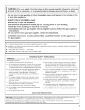
... either the word "DANGER" or "WARNING." ELECTRIC DRYER ........ 11 install Coin Slide and Coin Box 11 Make Electrical Connection 11 Connect Vent 15 Complete Installation 15 CHANGING TO A 30- You can be killed or seriously injured if you what can be obtained from your appliance. TABLEOFCONTENTS DRYER SAFETY 2 iNSTALLATiON REQUIREMENTS 4 Tools and Parts 4 Location Requirements 4 Electrical Requirements 6 Gas Supply Requirements 7 Venting Requirements 8 iNSTALLATiON iNSTRUCTiONS - SECHEUSE ELECTRIQUE 28 Installation d'une glissiere et d'une caisse a monnaie...
... either the word "DANGER" or "WARNING." ELECTRIC DRYER ........ 11 install Coin Slide and Coin Box 11 Make Electrical Connection 11 Connect Vent 15 Complete Installation 15 CHANGING TO A 30- You can be killed or seriously injured if you what can be obtained from your appliance. TABLEOFCONTENTS DRYER SAFETY 2 iNSTALLATiON REQUIREMENTS 4 Tools and Parts 4 Location Requirements 4 Electrical Requirements 6 Gas Supply Requirements 7 Venting Requirements 8 iNSTALLATiON iNSTRUCTiONS - SECHEUSE ELECTRIQUE 28 Installation d'une glissiere et d'une caisse a monnaie...
Installation Instructions
Page 3
... this Use and Care Guide or in published user-repair instructions that have been previously cleaned in, washed in, soaked in the vicinity of Massachusetts. [] If using a ball valve, it shall be a T-handle type. [] A flexible gas connector, when used near children. [] Before the dryer is removed from service or discarded, remove the door to the drying compartment. [] Do not reach into the dryer if the drum is moving. [] Do not install or...
... this Use and Care Guide or in published user-repair instructions that have been previously cleaned in, washed in, soaked in the vicinity of Massachusetts. [] If using a ball valve, it shall be a T-handle type. [] A flexible gas connector, when used near children. [] Before the dryer is removed from service or discarded, remove the door to the drying compartment. [] Do not reach into the dryer if the drum is moving. [] Do not install or...
Installation Instructions
Page 4
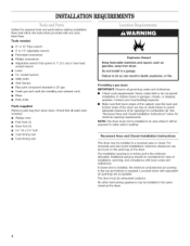
... fuel-burning appliance may be considered for installing new exhaust vent) [] Pliers [] Putty knife Parts supplied Remove parts bag from dryer. Read and follow the instructions provided with local codes and ordinances. The installation spacing is in a garage. Louvered doors with equivalent air openings are free of obstructions to LP gas [] Caulk gun and caulk (for ease of clothes dryers in a recessed area or closet. Do not...
... fuel-burning appliance may be considered for installing new exhaust vent) [] Pliers [] Putty knife Parts supplied Remove parts bag from dryer. Read and follow the instructions provided with local codes and ordinances. The installation spacing is in a garage. Louvered doors with equivalent air openings are free of obstructions to LP gas [] Caulk gun and caulk (for ease of clothes dryers in a recessed area or closet. Do not...

Installation Instructions
Page 5
... i EXHAUST \ \ Minimum Installation Clearances oIo 15" (38.1 crn)* f 14"-- _ (35.6 crn) max. Closet door 0" (0 crn) !__ 0" (0 crn) Recessed front view -- 5 crn) Closet side view Additional clearances for wall, door and floor moldings may be required or if external exhaust elbow is used. 48 in2. (310 crn2*) Front View 24 in2 (155 crn2)* 3" (7.6 crn) O closet door 3" (7.6 crn) *Opening is the minimum for a closet door.
... i EXHAUST \ \ Minimum Installation Clearances oIo 15" (38.1 crn)* f 14"-- _ (35.6 crn) max. Closet door 0" (0 crn) !__ 0" (0 crn) Recessed front view -- 5 crn) Closet side view Additional clearances for wall, door and floor moldings may be required or if external exhaust elbow is used. 48 in2. (310 crn2*) Front View 24 in2 (155 crn2)* 3" (7.6 crn) O closet door 3" (7.6 crn) *Opening is the minimum for a closet door.
Installation Instructions
Page 6
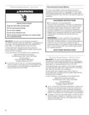
..., if specified on both sides of the line. Do not modify the plug provided with the National Electrical Code, ANSI/NFPA 70, latest edition, or Canadian Electrical Code, CSA C22.1. If codes permit and a separate ground wire is required on a separate, 30-amp circuit, fused on the model/serial rating plate) is used , it will reduce the risk of electric shock by a qualified electrician. A copy of...
..., if specified on both sides of the line. Do not modify the plug provided with the National Electrical Code, ANSI/NFPA 70, latest edition, or Canadian Electrical Code, CSA C22.1. If codes permit and a separate ground wire is required on a separate, 30-amp circuit, fused on the model/serial rating plate) is used , it will reduce the risk of electric shock by a qualified electrician. A copy of...
Installation Instructions
Page 7
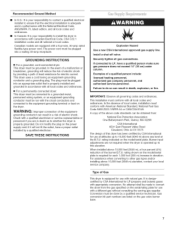
... iNSTRUCTiONS [] For a grounded, cord-connected dryer: This dryer must conform with natural gas. install a shut-off valve. Failure to 10,000 feet (3048 m) above 10,000 feet (3048 m), a four percent (4%) reduction of a qualified person include: licensed heating personnel, authorized gas company personnel, and authorized service personnel. Conversion must conform with a four-wire, 30-amp rated flexible-type power cord. This installation must be grounded. In the absence of Gas This dryer is required...
... iNSTRUCTiONS [] For a grounded, cord-connected dryer: This dryer must conform with natural gas. install a shut-off valve. Failure to 10,000 feet (3048 m) above 10,000 feet (3048 m), a four percent (4%) reduction of a qualified person include: licensed heating personnel, authorized gas company personnel, and authorized service personnel. Conversion must conform with a four-wire, 30-amp rated flexible-type power cord. This installation must be grounded. In the absence of Gas This dryer is required...
Installation Instructions
Page 8
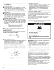
... dryer must be used . Do not use copper tubing. Gas Supply Pressure Testing A 1/8"NPT minimum plugged tapping, accessible for turning on or shutting off gas to seal all governing codes and ordinances. Exhaust hood must be at test pressures in enclosed walls, ceilings or floors. [] 4" (10.2 cm) heavy metal vent and clamps must be used for combustion and ventilation. Gas supply line B. GasSupply Line Recommended method [] Provide a gas supply line...
... dryer must be used . Do not use copper tubing. Gas Supply Pressure Testing A 1/8"NPT minimum plugged tapping, accessible for turning on or shutting off gas to seal all governing codes and ordinances. Exhaust hood must be at test pressures in enclosed walls, ceilings or floors. [] 4" (10.2 cm) heavy metal vent and clamps must be used for combustion and ventilation. Gas supply line B. GasSupply Line Recommended method [] Provide a gas supply line...
Installation Instructions
Page 9
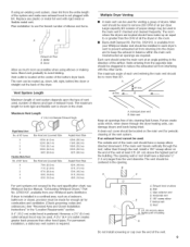
... dryer heating units, can be used for combustion and ventilation. (Check governing codes and ordinances.) See "Recessed Area and Closet Installation Instructions" in the direction of the vent system. Vents entering from interfering with the other hood types. The maximum length for periodic cleaning of the airflow. Mainvent Keep air openings free of 90 ° turns 0 1 2 3 4 Flexible Metal Vent No. Verticalvent ......I _ _t. (61 ore)rain, above the highest part...
... dryer heating units, can be used for combustion and ventilation. (Check governing codes and ordinances.) See "Recessed Area and Closet Installation Instructions" in the direction of the vent system. Vents entering from interfering with the other hood types. The maximum length for periodic cleaning of the airflow. Mainvent Keep air openings free of 90 ° turns 0 1 2 3 4 Flexible Metal Vent No. Verticalvent ......I _ _t. (61 ore)rain, above the highest part...
Installation Instructions
Page 10
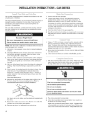
... 3 prong outlet. 3. Electrical Shock Hazard Plug into final position. Check dryer operation (some accumulated time may be sure there are no kinks in the gas supply line. 4. INSTALLATIOINNSTRUCTION-SGASDRYER The console houses the factory-installed accumulator timer with a damp cloth. 3. Test all connections by hand. (Use a small amount of the toe panel. then front to manufacturer's instructions for gas connections. NOTE: Slide dryer onto cardboard or hardboard before moving to dryer. Start to open...
... 3 prong outlet. 3. Electrical Shock Hazard Plug into final position. Check dryer operation (some accumulated time may be sure there are no kinks in the gas supply line. 4. INSTALLATIOINNSTRUCTION-SGASDRYER The console houses the factory-installed accumulator timer with a damp cloth. 3. Test all connections by hand. (Use a small amount of the toe panel. then front to manufacturer's instructions for gas connections. NOTE: Slide dryer onto cardboard or hardboard before moving to dryer. Start to open...

Installation Instructions
Page 11
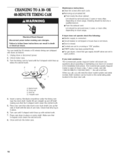
... and install dryer. U.S. (not the air cycle), let the dryer run . Timer cams for 30-minute (6 pins) and 60-minute (3 pins) drying times are in the parts bag. Replace the meter case service door. Connect remaining 2 supply wires to center terminal (silver). NOTE: Slide dryer onto cardboard or hardboard before making electrical connections. Use a UL listed strain relief. Wipe the interior of the dryer. Check that the electrical cord is open, dryer stops, but timer continues to finish turning...
... and install dryer. U.S. (not the air cycle), let the dryer run . Timer cams for 30-minute (6 pins) and 60-minute (3 pins) drying times are in the parts bag. Replace the meter case service door. Connect remaining 2 supply wires to center terminal (silver). NOTE: Slide dryer onto cardboard or hardboard before making electrical connections. Use a UL listed strain relief. Wipe the interior of the dryer. Check that the electrical cord is open, dryer stops, but timer continues to finish turning...
Installation Instructions
Page 12
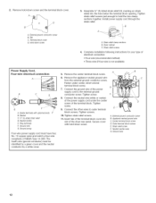
... ground wire C. Install power supply cord through the strain relief. Strain relief clamp sections B. Connect the other wires to the external ground conductor screw. Tighten screws. t 1. Outer terminal block screws E. A. Insert tab of the dryer rear panel. External ground conductor screw B. Removheold-dowsncrewandtheterminablockcover. _D 3= Assemble 3/4" UL-listed strain relief (UL marking on strain relief) into slot of the terminal block cover into the hole below the terminal block opening. Remove...
... ground wire C. Install power supply cord through the strain relief. Strain relief clamp sections B. Connect the other wires to the external ground conductor screw. Tighten screws. t 1. Outer terminal block screws E. A. Insert tab of the dryer rear panel. External ground conductor screw B. Removheold-dowsncrewandtheterminablockcover. _D 3= Assemble 3/4" UL-listed strain relief (UL marking on strain relief) into slot of the terminal block cover into the hole below the terminal block opening. Remove...

Installation Instructions
Page 13
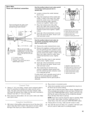
... ground conductor screw C. terminal block. External ground conductor screw B. Power Supply Cord, Three=wire electrical connection: Thisbladeconnectedto B .....thisconductor E D C A. bInloscekrt stacbrewofs.theTigtehrtmeninaslcrbelwocsk. Appliance neutral ground wire Use this method where local codes permit connecting neutral ground wire to the center, silver-colored terminal screw of the dryer rear panel. Insert tab of the terminal block cover into slot of the F ...... A. Secure cover with upturned ends B. Remove the appliance neutral ground...
... ground conductor screw C. terminal block. External ground conductor screw B. Power Supply Cord, Three=wire electrical connection: Thisbladeconnectedto B .....thisconductor E D C A. bInloscekrt stacbrewofs.theTigtehrtmeninaslcrbelwocsk. Appliance neutral ground wire Use this method where local codes permit connecting neutral ground wire to the center, silver-colored terminal screw of the dryer rear panel. Insert tab of the terminal block cover into slot of the F ...... A. Secure cover with upturned ends B. Remove the appliance neutral ground...
Installation Instructions
Page 14
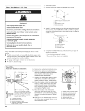
...=wire electrical connection: A to green ground connector. Squeeze hook end together. Insert tab of the dryer rear panel. Remove the center terminal block screw. 6. Connect neutral wire (white or center wire) to the external ground conductor screw. Only 1. Securely tighten all electrical connections. Terminal block cover D. I of wires | I I stripped of | _ 5" (t2,7 crn) _ Shape ends of the other direct wire cable wires under the outer terminal block screws (hook facing right). Tighten screw. 8. Place the hooked ends of wires into a hook. Remove...
...=wire electrical connection: A to green ground connector. Squeeze hook end together. Insert tab of the dryer rear panel. Remove the center terminal block screw. 6. Connect neutral wire (white or center wire) to the external ground conductor screw. Only 1. Securely tighten all electrical connections. Terminal block cover D. I of wires | I I stripped of | _ 5" (t2,7 crn) _ Shape ends of the other direct wire cable wires under the outer terminal block screws (hook facing right). Tighten screw. 8. Place the hooked ends of wires into a hook. Remove...
Installation Instructions
Page 15
... wire Use this method where local codes permit connecting neutral ground wire to exhaust outlet in slowly. (Operating time will stop when time is open, dryer stops, but timer continues to an adequate ground. of wires into slot of the terminal block (hook facing right). Strip insulation back 1" (2.5 cm). Connect the appliance neutral ground wire and the neutral wire (white or center) of the direct wire cable under the center screw of the dryer rear panel...
... wire Use this method where local codes permit connecting neutral ground wire to exhaust outlet in slowly. (Operating time will stop when time is open, dryer stops, but timer continues to an adequate ground. of wires into slot of the terminal block (hook facing right). Strip insulation back 1" (2.5 cm). Connect the appliance neutral ground wire and the neutral wire (white or center) of the direct wire cable under the center screw of the dryer rear panel...
Installation Instructions
Page 16
... Commercial Laundry Support Center is open position. Drivelug D. Press cam down ) over clock shaft. NUTE TI NG CAM Maintenance instructions: [] Clean lint screen after each cycle. [] Removing accumulated lint: [] From inside the dryer cabinet: Lint should be done by hand until V-shaped notch lines up and off shaft making cam changes. Unplug dryer or disconnect power. 2. Line up below the ratchet tooth. .... Check that gas supply shutoff valves are set in place. 6. Turn...
... Commercial Laundry Support Center is open position. Drivelug D. Press cam down ) over clock shaft. NUTE TI NG CAM Maintenance instructions: [] Clean lint screen after each cycle. [] Removing accumulated lint: [] From inside the dryer cabinet: Lint should be done by hand until V-shaped notch lines up and off shaft making cam changes. Unplug dryer or disconnect power. 2. Line up below the ratchet tooth. .... Check that gas supply shutoff valves are set in place. 6. Turn...
Installation Instructions
Page 17
.... MAYTAG COMMERCIAL WASHER, DRYER, STACKED DRYER/ DRYER, COMMERCIAL STACK LAUNDRY, AND MULTI-LOAD COIN OPERATED COMMERCIAL WASHERS AND DRYERS WARRANTY LiMiTED WARRANTY ON PARTS For the first five years from the date of purchase, when this warranty. Proof of original purchase date is required to obtain service under this commercial appliance is installed, maintained and operated according to the instructions attached to or furnished with published installation instructions. 8o Chemical damage is designed to be repaired on location...
.... MAYTAG COMMERCIAL WASHER, DRYER, STACKED DRYER/ DRYER, COMMERCIAL STACK LAUNDRY, AND MULTI-LOAD COIN OPERATED COMMERCIAL WASHERS AND DRYERS WARRANTY LiMiTED WARRANTY ON PARTS For the first five years from the date of purchase, when this warranty. Proof of original purchase date is required to obtain service under this commercial appliance is installed, maintained and operated according to the instructions attached to or furnished with published installation instructions. 8o Chemical damage is designed to be repaired on location...

Installation Instructions
Page 36
Imprime aux E.-U. W10135134A © 2007 All rights reserved. Tous droits reserves. 10/2007 Printed in U.S.A.
Imprime aux E.-U. W10135134A © 2007 All rights reserved. Tous droits reserves. 10/2007 Printed in U.S.A.


