

User Manual
Page 3
...blocked by the product manufacturer as the original plug. 15.Outdoor Antenna Grounding - Do not use liquid cleaners or aerosol cleaners. If replacement of power supply to the product. Any mounting of the polarized plug. This is a safety feature. See Figure 1. 8. The... openings should be sure the service technician has used a replacement plug specified by the manufacturer, or sold with Canadian ICES-003. This product may cause hazards. 7. IMPORTANT SAFETY INSTRUCTIONS READ BEFORE OPERATING...
...blocked by the product manufacturer as the original plug. 15.Outdoor Antenna Grounding - Do not use liquid cleaners or aerosol cleaners. If replacement of power supply to the product. Any mounting of the polarized plug. This is a safety feature. See Figure 1. 8. The... openings should be sure the service technician has used a replacement plug specified by the manufacturer, or sold with Canadian ICES-003. This product may cause hazards. 7. IMPORTANT SAFETY INSTRUCTIONS READ BEFORE OPERATING...

User Manual
Page 4
...often require extensive work by following conditions: a. An outside antenna system, extreme care should not be sure the service technician has used replacement parts specified by the manufacturer. 25.Heat - Never spill liquid of any kind into this product, ask the service technician to perform..., or when it from the wall outlet and refer servicing to this product through openings as this indicates a need for service. 22.Replacement Parts - 16.Lightning - For added protection for long periods of any way, and f. The product should be situated away from touching...
...often require extensive work by following conditions: a. An outside antenna system, extreme care should not be sure the service technician has used replacement parts specified by the manufacturer. 25.Heat - Never spill liquid of any kind into this product, ask the service technician to perform..., or when it from the wall outlet and refer servicing to this product through openings as this indicates a need for service. 22.Replacement Parts - 16.Lightning - For added protection for long periods of any way, and f. The product should be situated away from touching...

User Manual
Page 11
...with correct (+) and (-) polarity. 3. Close the battery cover until it clicks. 7 Remove the battery cover Appr1o6xifmeeatte(5lym) 60 Remote control unit ZS5300 Note : • Do not use the rechargeable batteries(Ni-Cd type). 2. If the transmitter is an obstacle between them as soon as possible..., when you notice that the batteries are starting to a direction other than the IR SENSOR or if there is pointed to run down, replace them , remote control may not be possible. • Remote control operating range 2. Remote control Operate the remote control unit (RC5300ZS) within...
...with correct (+) and (-) polarity. 3. Close the battery cover until it clicks. 7 Remove the battery cover Appr1o6xifmeeatte(5lym) 60 Remote control unit ZS5300 Note : • Do not use the rechargeable batteries(Ni-Cd type). 2. If the transmitter is an obstacle between them as soon as possible..., when you notice that the batteries are starting to a direction other than the IR SENSOR or if there is pointed to run down, replace them , remote control may not be possible. • Remote control operating range 2. Remote control Operate the remote control unit (RC5300ZS) within...
User Manual
Page 12
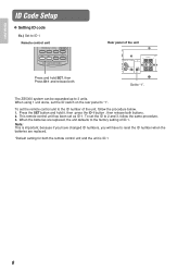
... unit and the unit is important, because if you have changed ID numbers, you will have to reset the ID number when the batteries are replaced, the unit defaults to the factory setting of ID-1. Rear panel of the unit, follow the same procedure. 3. To set the ID to 2 and 3, follow... OUT ZONE DIRECT IN R L R L SPEAKERS (MINIMUM 6 OHMS) ZONE 1 ZONE 2 ZONE 3 R L R L R L 1 STATUS OUT REMOTE CONTROL ID ZONE 1 ZONE 3 SELECTOR 2 IN EXT. Note: This is ID-1 8 The ZS5300 system can be expanded up to "1". To set the remote control unit to "1".
... unit and the unit is important, because if you have changed ID numbers, you will have to reset the ID number when the batteries are replaced, the unit defaults to the factory setting of ID-1. Rear panel of the unit, follow the same procedure. 3. To set the ID to 2 and 3, follow... OUT ZONE DIRECT IN R L R L SPEAKERS (MINIMUM 6 OHMS) ZONE 1 ZONE 2 ZONE 3 R L R L R L 1 STATUS OUT REMOTE CONTROL ID ZONE 1 ZONE 3 SELECTOR 2 IN EXT. Note: This is ID-1 8 The ZS5300 system can be expanded up to "1". To set the remote control unit to "1".


