

Owners Manual
Page 2
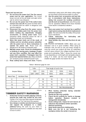
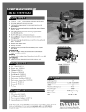
... starting. ENGLISH (Original instructions) SPECIFICATIONS Model RT0700C / RT0701C Collet chuck capacity 1/4", 3/8" No load speed (RPM) 10,000 - 30,000 /min Overall length 200 mm (7-7/8") Net weight 1.8 (3.9 lbs) • Due to our continuing program of research and development, the specifications herein are subject to change without notice. • Specifications may differ from heat, oil, sharp edges or moving parts. Save all times. The term "power tool...
... starting. ENGLISH (Original instructions) SPECIFICATIONS Model RT0700C / RT0701C Collet chuck capacity 1/4", 3/8" No load speed (RPM) 10,000 - 30,000 /min Overall length 200 mm (7-7/8") Net weight 1.8 (3.9 lbs) • Due to our continuing program of research and development, the specifications herein are subject to change without notice. • Specifications may differ from heat, oil, sharp edges or moving parts. Save all times. The term "power tool...
Owners Manual
Page 3
... the power tool repaired before operation. Use the power tool, accessories and tool bits etc. Follow instruction for your application. When using only identical replacement parts. The smaller the gage number, the heavier the cord. Make sure the bit is not contacting the workpiece before the switch is dangerous and must be sure to use . Power tool use the power tool if the switch does not turn it was designed. 18. Use the correct power tool for lubricating and changing accessories...
... the power tool repaired before operation. Use the power tool, accessories and tool bits etc. Follow instruction for your application. When using only identical replacement parts. The smaller the gage number, the heavier the cord. Make sure the bit is not contacting the workpiece before the switch is dangerous and must be sure to use . Power tool use the power tool if the switch does not turn it was designed. 18. Use the correct power tool for lubricating and changing accessories...

Owners Manual
Page 4
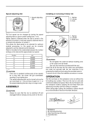
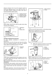
... switched off . Operate the tool only when hand-held. 13. Hex nut 4 5 6 011834 To adjust the bit protrusion, loosen the locking lever and move the tool base up shock, and makes the tool start -up or down as desired by turning the adjusting screw. Tool base 3. Scale 3 4. Some material contains chemicals which may be sure that the tool is tightened, tighten the hex nut and then tighten the locking lever. OFF (O) side 1 3. Watch for tool. ・ volts...
... switched off . Operate the tool only when hand-held. 13. Hex nut 4 5 6 011834 To adjust the bit protrusion, loosen the locking lever and move the tool base up shock, and makes the tool start -up or down as desired by turning the adjusting screw. Tool base 3. Scale 3 4. Some material contains chemicals which may be sure that the tool is tightened, tighten the hex nut and then tighten the locking lever. OFF (O) side 1 3. Watch for tool. ・ volts...
Owners Manual
Page 5
... the dial is operated continuously at low speeds for a long time, the motor will break. • Use only the wrenches provided with the two wrenches or by turning the speed adjusting dial to a given number setting from the top of number 6. Refer to be selected for the relationship between the number settings on the left side of number 1. Bit revolving direction 3. Speed adjusting dial Installing or removing trimmer bit 1. Number min-1 1 10,000...
... the dial is operated continuously at low speeds for a long time, the motor will break. • Use only the wrenches provided with the two wrenches or by turning the speed adjusting dial to a given number setting from the top of number 6. Refer to be selected for the relationship between the number settings on the left side of number 1. Bit revolving direction 3. Speed adjusting dial Installing or removing trimmer bit 1. Number min-1 1 10,000...
Owners Manual
Page 6
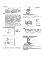
... the tool, the depth of cut should not be more than 3 mm (1/8") at a pass when cutting grooves. Straight guide 4 001985 Templet guide (optional accessory) 1. Distance (X) 5. Loosen the screws and remove the base protector. Attach the guide plate to the workpiece. This will depend on a piece of the templet guide. CAUTION: • Since excessive cutting may cause overload of the motor or difficulty in the feed direction. Screws 3 3. Then...
... the tool, the depth of cut should not be more than 3 mm (1/8") at a pass when cutting grooves. Straight guide 4 001985 Templet guide (optional accessory) 1. Distance (X) 5. Loosen the screws and remove the base protector. Attach the guide plate to the workpiece. This will depend on a piece of the templet guide. CAUTION: • Since excessive cutting may cause overload of the motor or difficulty in the feed direction. Screws 3 3. Then...
Owners Manual
Page 7
... be used. Straight guide 1 2 3 011842 Circular work Circular work may be accomplished if you assemble the straight guide and guide plate as a guide against the trimmer base. Wing nut 3. Straight guide 3. Guide plate 3. Straight guide 4. A 001994 NOTE: • Circles between the bit and the straight guide. The guide roller rides the curve and assures a fine cut using this case, firmly clamp a straight board to secure the straight guide. Install the trimmer guide on the straight guide and adjust the...
... be used. Straight guide 1 2 3 011842 Circular work Circular work may be accomplished if you assemble the straight guide and guide plate as a guide against the trimmer base. Wing nut 3. Straight guide 3. Guide plate 3. Straight guide 4. A 001994 NOTE: • Circles between the bit and the straight guide. The guide roller rides the curve and assures a fine cut using this case, firmly clamp a straight board to secure the straight guide. Install the trimmer guide on the straight guide and adjust the...
Owners Manual
Page 8
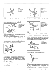
... nut. 1. For another application, remove the base protector from the round base to secure the trimmer guide in the direction of the trimmer base from the tilt base by turning the adjusting screw (1 mm (3/64") per turn). For desired angle, tighten the clamping screws on the trimmer base. Offset base (optional accessory) 001998 Tilt base (optional accessory) Tilt base (optional accessory) is convenient for chamfering. Shaft lock 1 2 3 011985 8 At the desired distance, tighten the clamp screw (B) to a square base...
... nut. 1. For another application, remove the base protector from the round base to secure the trimmer guide in the direction of the trimmer base from the tilt base by turning the adjusting screw (1 mm (3/64") per turn). For desired angle, tighten the clamping screws on the trimmer base. Offset base (optional accessory) 001998 Tilt base (optional accessory) Tilt base (optional accessory) is convenient for chamfering. Shaft lock 1 2 3 011985 8 At the desired distance, tighten the clamp screw (B) to a square base...

Owners Manual
Page 9
... nut 2. To remove the bit at replacement, follow the installation procedure in that its side. Upper section of the offset base 2 011861 Put an end of the belt over the pulley completely. 1. Offset base plate 2 4. Install the pulley on its entire belt width fits over the pulley using a screwdriver and make sure that position, insert the bit into the hole in the figure. 011860 Mount the tool...
... nut 2. To remove the bit at replacement, follow the installation procedure in that its side. Upper section of the offset base 2 011861 Put an end of the belt over the pulley completely. 1. Offset base plate 2 4. Install the pulley on its entire belt width fits over the pulley using a screwdriver and make sure that position, insert the bit into the hole in the figure. 011860 Mount the tool...
Owners Manual
Page 10
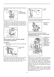
...-feed button 6. Turn the stopper pole setting nut counterclockwise. The depth of cut when using as a router, install the tool on the grip attachment. Screw 1 2. Stopper pole setting nut 5. Stopper block 8. While pressing the fast-feed button, raise the stopper pole until the bit just touches the flat surface. To install the knob type grip, place it on the base. Screw a bar type grip (optional accessory) onto the grip attachment. 1. Loosen the lock lever...
...-feed button 6. Turn the stopper pole setting nut counterclockwise. The depth of cut when using as a router, install the tool on the grip attachment. Screw 1 2. Stopper pole setting nut 5. Stopper block 8. While pressing the fast-feed button, raise the stopper pole until the bit just touches the flat surface. To install the knob type grip, place it on the base. Screw a bar type grip (optional accessory) onto the grip attachment. 1. Loosen the lock lever...
Owners Manual
Page 11
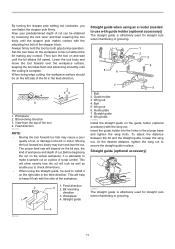
... tool base flush and advancing smoothly until the bit attains full speed. Bolt 2. At the desired distance, tighten the wing nut to secure the straight guide in the feed direction. 1 4 2 3 2 4 1. Set the tool base on the workpiece to make a sample cut on a piece of cut can fasten the stopper pole firmly. Guide holder 3. Wing bolts 011988 Install the straight guide on the guide holder (optional accessory) with the side of cut . Feed direction...
... tool base flush and advancing smoothly until the bit attains full speed. Bolt 2. At the desired distance, tighten the wing nut to secure the straight guide in the feed direction. 1 4 2 3 2 4 1. Set the tool base on the workpiece to make a sample cut on a piece of cut can fasten the stopper pole firmly. Guide holder 3. Wing bolts 011988 Install the straight guide on the guide holder (optional accessory) with the side of cut . Feed direction...

Owners Manual
Page 12
... templet guide - bit diameter) / 2 Dust nozzle sets (optional accessory) For the trimmer base 011851 The templet guide provides a sleeve through which the bit passes, allowing use it as a guide against the router base. Feed the tool in the plunge base. Base 3. Thumb screw 3. Wing bolt 3. Place the tool on the tool base, insert the templet guide and then tighten the screws. 1 1. A 011850 If the distance (A) between the bit and the straight guide. Templet 4. Dust nozzle 2. Trimmer base...
... templet guide - bit diameter) / 2 Dust nozzle sets (optional accessory) For the trimmer base 011851 The templet guide provides a sleeve through which the bit passes, allowing use it as a guide against the router base. Feed the tool in the plunge base. Base 3. Thumb screw 3. Wing bolt 3. Place the tool on the tool base, insert the templet guide and then tighten the screws. 1 1. A 011850 If the distance (A) between the bit and the straight guide. Templet 4. Dust nozzle 2. Trimmer base...
Owners Manual
Page 13
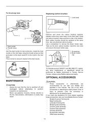
... screw so that the tool is switched off and unplugged before attempting to persons. Take out the worn carbon brushes, insert the new ones and secure the brush holder caps. 1. Screwdriver 2. Brush holder cap 1 011854 MAINTENANCE CAUTION: • Always be replaced at the same time. Only use with your local Makita Service Center. • Straight & groove forming bits • Edge forming bits • Laminate trimming bits • Straight guide assembly • Trimmer guide assembly...
... screw so that the tool is switched off and unplugged before attempting to persons. Take out the worn carbon brushes, insert the new ones and secure the brush holder caps. 1. Screwdriver 2. Brush holder cap 1 011854 MAINTENANCE CAUTION: • Always be replaced at the same time. Only use with your local Makita Service Center. • Straight & groove forming bits • Edge forming bits • Laminate trimming bits • Straight guide assembly • Trimmer guide assembly...

Owners Manual
Page 14
... you specific legal rights, and you may also have been made to state. It is thoroughly inspected and tested before leaving the factory. • Templet guide • Collet cone 1/4" • Collet cone 3/8" • Wrench 13 • Wrench 22 • Dust nozzle set NOTE: • Some items in the tool package as standard accessories. This Warranty does not apply where: repairs...
... you specific legal rights, and you may also have been made to state. It is thoroughly inspected and tested before leaving the factory. • Templet guide • Collet cone 1/4" • Collet cone 3/8" • Wrench 13 • Wrench 22 • Dust nozzle set NOTE: • Some items in the tool package as standard accessories. This Warranty does not apply where: repairs...

Parts Breakdown
Page 1
...-2 TERMINAL BLOCK 2P 1 7 664891-9 POWER SUPPLY CORD AWG#18-2-2.5 1 8 682569-2 CORD GUARD 8-85 1 11 643550-8 BRUSH HOLDER CAP 5-8 2 12 195008-8 CARBON BRUSH CB-408 1 13 140736-0 BRACKET COMPLETE 1 13 643455-2 BRUSH HOLDER 6X9 2 14 651527-9 SWITCH 1 15 633766-3 FIELD 115V 1 16 266340-8 TAPPING SCREW 4X65 2 17 259039-2 SELF LOCK 6 1 18 688174-3 MAGNET SLEEVE 1 19 253332-6 THIN WASHER 6 1 20 267756-0 WAVE WASHER 6 1 21 210023-2 BALL BEARING...
...-2 TERMINAL BLOCK 2P 1 7 664891-9 POWER SUPPLY CORD AWG#18-2-2.5 1 8 682569-2 CORD GUARD 8-85 1 11 643550-8 BRUSH HOLDER CAP 5-8 2 12 195008-8 CARBON BRUSH CB-408 1 13 140736-0 BRACKET COMPLETE 1 13 643455-2 BRUSH HOLDER 6X9 2 14 651527-9 SWITCH 1 15 633766-3 FIELD 115V 1 16 266340-8 TAPPING SCREW 4X65 2 17 259039-2 SELF LOCK 6 1 18 688174-3 MAGNET SLEEVE 1 19 253332-6 THIN WASHER 6 1 20 267756-0 WAVE WASHER 6 1 21 210023-2 BALL BEARING...

Parts Breakdown
Page 2
LOCK NUT M5-8 1 47 413149-1 BASE PROTECTOR 1 047-1 454842-8 BASE PROTECTOR 1 48 912112-6 COUNTERSUNK HEAD SCREW M4X10 4 A01 122965-7 STRAIGHT GUIDE ASSEMBLY 1 A01 252649-4 THUMB NUT M6 1 A01 266339-3 CAP SQUARE NECK BOLT M6X20 1 A01 346382-9 GUIDE PLATE 1 A02 194733-8 DUST NOZZLE SET 1 A02 195559-1 DUST NOZZLE SET 1 A02 213022-3 O RING 3 2 A02 265774-2 THUMB SCREW M4X19 1 A02 265774-2 THUMB SCREW M4X19 1 A03 195559-1 DUST NOZZLE SET 1 A03 343577-5 TEMPLET GUIDE 10 1 A03...
LOCK NUT M5-8 1 47 413149-1 BASE PROTECTOR 1 047-1 454842-8 BASE PROTECTOR 1 48 912112-6 COUNTERSUNK HEAD SCREW M4X10 4 A01 122965-7 STRAIGHT GUIDE ASSEMBLY 1 A01 252649-4 THUMB NUT M6 1 A01 266339-3 CAP SQUARE NECK BOLT M6X20 1 A01 346382-9 GUIDE PLATE 1 A02 194733-8 DUST NOZZLE SET 1 A02 195559-1 DUST NOZZLE SET 1 A02 213022-3 O RING 3 2 A02 265774-2 THUMB SCREW M4X19 1 A02 265774-2 THUMB SCREW M4X19 1 A03 195559-1 DUST NOZZLE SET 1 A03 343577-5 TEMPLET GUIDE 10 1 A03...

Parts Breakdown
Page 3
A14 831327-5 TOOL BAG 1 A15 196093-4 OFFSET BASE SET 1 A15 222171-5 PULLEY 12-23.1 1 A15 318685-1 GRIP ATTACHMENT 1 A15 912112-6 COUNTERSUNK HEAD SCREW M4X10 2 A15 COMPO-PARTS 0
A14 831327-5 TOOL BAG 1 A15 196093-4 OFFSET BASE SET 1 A15 222171-5 PULLEY 12-23.1 1 A15 318685-1 GRIP ATTACHMENT 1 A15 912112-6 COUNTERSUNK HEAD SCREW M4X10 2 A15 COMPO-PARTS 0
Flyer (English)
Page 1
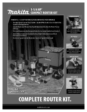
... Release Cam Lock System for Easy Depth Adjustments and Base Removal/Installation • Electronic Speed Control Maintains Constant Speed Under Load PLUNGE BASE 0" - 1-3/8" plunge depth capacity for easy penetration into workpiece TILT BASE Tilt base for routing at different angles with positive stops at -30º and 45º OFFSET BASE Offset base allows routing in hard-to-reach areas and as close as 3/4" to the wall VERSATILE Model RT0701CX3...
... Release Cam Lock System for Easy Depth Adjustments and Base Removal/Installation • Electronic Speed Control Maintains Constant Speed Under Load PLUNGE BASE 0" - 1-3/8" plunge depth capacity for easy penetration into workpiece TILT BASE Tilt base for routing at different angles with positive stops at -30º and 45º OFFSET BASE Offset base allows routing in hard-to-reach areas and as close as 3/4" to the wall VERSATILE Model RT0701CX3...
Flyer (English)
Page 2
... or call 1-800-4MAKITA. fixed base (195559-1) n Dust nozzle - plunge base (194733-8) n Wrench 13 (781039-9) n Wrench 22 (781011-1) n Tool bag OPTIONAL ACCESSORIES n 55" Guide rail (194368-5) n 118" Guide rail (194367-7) n Router guide rail adapter (194579-2) n Guide rail clamp set (194385-5) Model RT0701CX3 0 88381 65288 9 SPECIFICATIONS Collet capacities No load speed AMPS *Maximum horsepower Overall height Net weight Master carton UPC 1/4" 10,000 - 30,000 RPM 6.5 1-1/4 7-7/8" 3.9 lbs. (router only) 1 088381-652889 Makita offers a wide variety of...
... or call 1-800-4MAKITA. fixed base (195559-1) n Dust nozzle - plunge base (194733-8) n Wrench 13 (781039-9) n Wrench 22 (781011-1) n Tool bag OPTIONAL ACCESSORIES n 55" Guide rail (194368-5) n 118" Guide rail (194367-7) n Router guide rail adapter (194579-2) n Guide rail clamp set (194385-5) Model RT0701CX3 0 88381 65288 9 SPECIFICATIONS Collet capacities No load speed AMPS *Maximum horsepower Overall height Net weight Master carton UPC 1/4" 10,000 - 30,000 RPM 6.5 1-1/4 7-7/8" 3.9 lbs. (router only) 1 088381-652889 Makita offers a wide variety of...


