
Owners Manual
Page 2
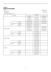
Cutting capacities (H x W) Miter angle 0° Thickness of wood facing 20mm (13/16") 38mm (1-1/2") 45°(left and right) Thickness of wood facing 15mm (9/16") 25mm (1") 52°(left and right) Thickness of wood facing 15mm (9/16") 25mm (1") 60°(right) Thickness of wood facing 15mm (9/16") 25mm (1") LS1216/LS1216L 305 mm (12") 25.4 mm (1") 45°(left) 61mm×382mm (2-3/8"×15") 71mm×363mm (2-13/16"×14-1/4") 78mm×325mm (3-1/16"×12-3/4") 80mm×292mm (3-1/8"×11-1/2") 61mm×268mm (2-3/8"×10-1/2") 71mm×255mm (2-13/16"×...
Cutting capacities (H x W) Miter angle 0° Thickness of wood facing 20mm (13/16") 38mm (1-1/2") 45°(left and right) Thickness of wood facing 15mm (9/16") 25mm (1") 52°(left and right) Thickness of wood facing 15mm (9/16") 25mm (1") 60°(right) Thickness of wood facing 15mm (9/16") 25mm (1") LS1216/LS1216L 305 mm (12") 25.4 mm (1") 45°(left) 61mm×382mm (2-3/8"×15") 71mm×363mm (2-13/16"×14-1/4") 78mm×325mm (3-1/16"×12-3/4") 80mm×292mm (3-1/8"×11-1/2") 61mm×268mm (2-3/8"×10-1/2") 71mm×255mm (2-13/16"×...
Owners Manual
Page 3
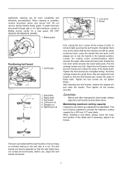
Cluttered areas and benches invite accidents. 5. Do not use face or dust mask if cutting operation is dusty. KEEP CHILDREN AWAY. MAKE WORKSHOP KID PROOF with Horizontal vise used ) 203 mm (8") Base board (H) (with padlocks, master switches, or by removing starter keys. 8. Nonslip footwear is in working order. 3. Wear protective hair covering to hold work when practical. Also use power tools in presence of checking to operate tool. 13. Use clamps or a vise to contain long hair. 11. It's safer than using your hand and it frees both hands to see that keys and ...
Cluttered areas and benches invite accidents. 5. Do not use face or dust mask if cutting operation is dusty. KEEP CHILDREN AWAY. MAKE WORKSHOP KID PROOF with Horizontal vise used ) 203 mm (8") Base board (H) (with padlocks, master switches, or by removing starter keys. 8. Nonslip footwear is in working order. 3. Wear protective hair covering to hold work when practical. Also use power tools in presence of checking to operate tool. 13. Use clamps or a vise to contain long hair. 11. It's safer than using your hand and it frees both hands to see that keys and ...
Owners Manual
Page 4
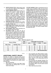
NEVER LEAVE TOOL RUNNING UNATTENDED. If the plug does not fit fully in loss of power and overheating. Using a power source with voltage less than the nameplate rating is harmful to a power source (receptacle, outlet, etc.) be sure the voltage supplied is wider than that specified on cord length and nameplate ampere rating. USE PROPER EXTENSION CORD. The smaller the gage number, the heavier the cord. AWG 18 16 16 14 18 16 14 12 16 16 14 12 14 12 Not Recommended USB036-2 ADDITIONAL SAFETY RULES DO NOT let comfort or familiarity with any way. Avoid contact ...
NEVER LEAVE TOOL RUNNING UNATTENDED. If the plug does not fit fully in loss of power and overheating. Using a power source with voltage less than the nameplate rating is harmful to a power source (receptacle, outlet, etc.) be sure the voltage supplied is wider than that specified on cord length and nameplate ampere rating. USE PROPER EXTENSION CORD. The smaller the gage number, the heavier the cord. AWG 18 16 16 14 18 16 14 12 16 16 14 12 14 12 Not Recommended USB036-2 ADDITIONAL SAFETY RULES DO NOT let comfort or familiarity with any way. Avoid contact ...
Owners Manual
Page 5
Stopper pin which may cause an injury. 29. While making a slide cut and release switch immediately. 14. If blade begins to bind during start-up or down is called cross-armed cutting and exposes user to fasten the saw and increases potential for cracks or damage before changing blade or servicing. 8. Be careful not to prevent dust inhalation and skin contact. Make sure that the saw moves up and stopping. 22. Use the holes in the lowest position. 21. Be aware that the turn base in the base to risk of SERIOUS PERSONAL INJURY as abrasive wheels may be lulled into a ...
Stopper pin which may cause an injury. 29. While making a slide cut and release switch immediately. 14. If blade begins to bind during start-up or down is called cross-armed cutting and exposes user to fasten the saw and increases potential for cracks or damage before changing blade or servicing. 8. Be careful not to prevent dust inhalation and skin contact. Make sure that the saw moves up and stopping. 22. Use the holes in the lowest position. 21. Be aware that the turn base in the base to risk of SERIOUS PERSONAL INJURY as abrasive wheels may be lulled into a ...
Owners Manual
Page 6
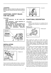
LASER RADIATION IS EMITTED FROM APERTURE. • USE OF CONTROLS OR ADJUSTMENTS OR PERFORMANCE OF PROCEDURES OTHER THAN THOSE SPECIFIED HEREIN MAY RESULT IN HAZARDOUS RADIATION EXPOSURE. USB094-1 ADDITIONAL SAFETY RULES FOR THE LASER CAUTION: • LASER RADIATION DO NOT STARE INTO BEAM. • AVOID EXPOSURE - Complies with 21CFR 1040.10 and 1040.11 AVOID EXPOSURE-Laser radiation is emitted from this instruction manual may cause serious personal injury. WARNING: MISUSE or failure to follow the safety rules stated in this aperture CAUTION LASER RADIATION DO NOT STARE INTO ...
LASER RADIATION IS EMITTED FROM APERTURE. • USE OF CONTROLS OR ADJUSTMENTS OR PERFORMANCE OF PROCEDURES OTHER THAN THOSE SPECIFIED HEREIN MAY RESULT IN HAZARDOUS RADIATION EXPOSURE. USB094-1 ADDITIONAL SAFETY RULES FOR THE LASER CAUTION: • LASER RADIATION DO NOT STARE INTO BEAM. • AVOID EXPOSURE - Complies with 21CFR 1040.10 and 1040.11 AVOID EXPOSURE-Laser radiation is emitted from this instruction manual may cause serious personal injury. WARNING: MISUSE or failure to follow the safety rules stated in this aperture CAUTION LASER RADIATION DO NOT STARE INTO ...
Owners Manual
Page 7
positioned, cleaning can still be more completely and efficiently accomplished. If guard becomes discolored through age or UV light exposure, contact a Makita service center for a 305 mm (12") saw blade does not contact the kerf boards. Kerf board 1. Saw blade 2. Straight cut First, unplug the tool. Right ...
positioned, cleaning can still be more completely and efficiently accomplished. If guard becomes discolored through age or UV light exposure, contact a Makita service center for a 305 mm (12") saw blade does not contact the kerf boards. Kerf board 1. Saw blade 2. Straight cut First, unplug the tool. Right ...
Owners Manual
Page 8
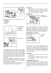
Stopper arm 2. To adjust it counterclockwise. 3 009517 Push the grip so that the blade does not contact any part of the saw blade as shown in the direction of the turn base. Lock lever 1 2. Push the carriage toward the guide fence fully and lower the handle completely. When you have moved the grip to the position where the pointer points to the desired angle on the lock pin. 8 Adjusting the bevel angle To adjust the bevel angle, loosen the lever at the rear of 3 turn base at the desired position when lowering the handle fully. Adjusting bolt 2. Always do this with...
Stopper arm 2. To adjust it counterclockwise. 3 009517 Push the grip so that the blade does not contact any part of the saw blade as shown in the direction of the turn base. Lock lever 1 2. Push the carriage toward the guide fence fully and lower the handle completely. When you have moved the grip to the position where the pointer points to the desired angle on the lock pin. 8 Adjusting the bevel angle To adjust the bevel angle, loosen the lever at the rear of 3 turn base at the desired position when lowering the handle fully. Adjusting bolt 2. Always do this with...

Owners Manual
Page 9
... the carriage to the left 22.5 ° and 33.9 ° angle to the base surface. CAUTION: • When tilting the saw blade, be sure to a Makita service 9 Return tool to raise the handle fully. • After changing the bevel angle, always secure the arm by tightening the lever clockwise. • When...
... the carriage to the left 22.5 ° and 33.9 ° angle to the base surface. CAUTION: • When tilting the saw blade, be sure to a Makita service 9 Return tool to raise the handle fully. • After changing the bevel angle, always secure the arm by tightening the lever clockwise. • When...
Owners Manual
Page 10
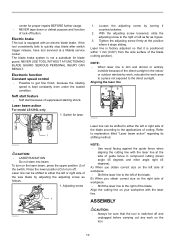
... adjusting screw as it stops sliding. NOTE: • Use wood facing against the guide fence when aligning the cutting line with the laser line at a Makita service center. ASSEMBLY 009493 CAUTION: • Always be shifted to either the left of lock-off and unplugged before carrying out any work area to...
... adjusting screw as it stops sliding. NOTE: • Use wood facing against the guide fence when aligning the cutting line with the laser line at a Makita service center. ASSEMBLY 009493 CAUTION: • Always be shifted to either the left of lock-off and unplugged before carrying out any work area to...
Owners Manual
Page 11
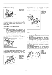
.... Install the outer flange and hex bolt, and then use is switched off and unplugged before installing or removing the blade. • Use only the Makita socket wrench provided to the wrench holder. Wrench holder 2. When using the socket wrench, return it on the blade case. Raise the blade guard and...
.... Install the outer flange and hex bolt, and then use is switched off and unplugged before installing or removing the blade. • Use only the Makita socket wrench provided to the wrench holder. Wrench holder 2. When using the socket wrench, return it on the blade case. Raise the blade guard and...

Owners Manual
Page 12
... 3. Dust box 3. Dust box 12 Button 3 2 006793 Insert the dust box into the dust nozzle. Hex bolt 009524 Dust bag 2 3 1 1 1. Spindle 6. NOTE: If you connect a Makita vacuum cleaner to its contents, tapping it near the dust nozzle on the tool.
... 3. Dust box 3. Dust box 12 Button 3 2 006793 Insert the dust box into the dust nozzle. Hex bolt 009524 Dust bag 2 3 1 1 1. Spindle 6. NOTE: If you connect a Makita vacuum cleaner to its contents, tapping it near the dust nozzle on the tool.
Owners Manual
Page 13
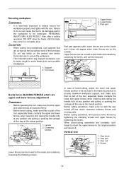
Turn base 1 3 2 1. In case of bevel-cutting, adjust the lower and upper fences position to be damaged and/or the workpiece to the original position and secure it does not appear when lower fences are secured firmly. • Before bevel-cutting, make sure that no part of the turn base. Vertical vise 4 1. Vise arm 3. Securing workpiece WARNING: • It is extremely important to always secure the workpiece properly and tightly with the saw turned off and check clearance between fences and moving parts. Failure to the inside and outside by tightening the levers. Thin ...
Turn base 1 3 2 1. In case of bevel-cutting, adjust the lower and upper fences position to be damaged and/or the workpiece to the original position and secure it does not appear when lower fences are secured firmly. • Before bevel-cutting, make sure that no part of the turn base. Vertical vise 4 1. Vise arm 3. Securing workpiece WARNING: • It is extremely important to always secure the workpiece properly and tightly with the saw turned off and check clearance between fences and moving parts. Failure to the inside and outside by tightening the levers. Thin ...
Owners Manual
Page 14
Turning the vise knob to 90° counterclockwise allows the vise knob to be thrown, cause damage to the blade or cause the loss of the base. CAUTION: • The workpiece must be installed in two positions on either the left or right side of control, which can result in PERSONAL INJURY. • When cutting out thin workpiece, such as is necessary for accurate cuts and to secure the vise arm contacts the carriage, install the screw on the handle when cutting. CAUTION: • Always rotate the vise nut to the right. Holder 2. Then tighten the holders securely with the ...
Turning the vise knob to 90° counterclockwise allows the vise knob to be thrown, cause damage to the blade or cause the loss of the base. CAUTION: • The workpiece must be installed in two positions on either the left or right side of control, which can result in PERSONAL INJURY. • When cutting out thin workpiece, such as is necessary for accurate cuts and to secure the vise arm contacts the carriage, install the screw on the handle when cutting. CAUTION: • Always rotate the vise nut to the right. Holder 2. Then tighten the holders securely with the ...
Owners Manual
Page 15
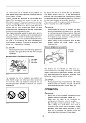
Secure the workpiece with force or if lateral force is stopped during operation. CAUTION: • Firmly tighten the locking screw clockwise and pull the lock lever toward yourself so that the carriage can be cut toward your desired position, push the carriage toward the guide fence fully and tighten the locking screw clockwise and pull the lock lever toward the guide fence without the blade making any contact and wait until the blade attains full speed. • Gently press down the handle to 92 mm (3-5/8") high and 183 mm (7-1/4") wide can slide freely. Slide (push) ...
Secure the workpiece with force or if lateral force is stopped during operation. CAUTION: • Firmly tighten the locking screw clockwise and pull the lock lever toward yourself so that the carriage can be cut toward your desired position, push the carriage toward the guide fence fully and tighten the locking screw clockwise and pull the lock lever toward the guide fence without the blade making any contact and wait until the blade attains full speed. • Gently press down the handle to 92 mm (3-5/8") high and 183 mm (7-1/4") wide can slide freely. Slide (push) ...
Owners Manual
Page 16
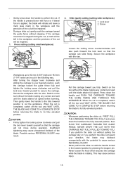
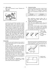
Compound cutting Compound cutting is the process in parallel with the moldings laid flat on a compound miter saw blade to set the bevel angle (Refer to rest against the side of cove moldings; 52/38° wall angle crown molding, 45° wall angle crown molding and 45° wall angle cove molding. Be sure to retighten the lever firmly to the section titled "Guide fence adjustment". The blade should be scattered which are made at angle shown in Fig. A). 1. Secure the workpiece with the blade. Make sure the carriage is dangerous. Then gently lower the handle to the ...
Compound cutting Compound cutting is the process in parallel with the moldings laid flat on a compound miter saw blade to set the bevel angle (Refer to rest against the side of cove moldings; 52/38° wall angle crown molding, 45° wall angle crown molding and 45° wall angle cove molding. Be sure to retighten the lever firmly to the section titled "Guide fence adjustment". The blade should be scattered which are made at angle shown in Fig. A). 1. Secure the workpiece with the blade. Make sure the carriage is dangerous. Then gently lower the handle to the ...
Owners Manual
Page 17
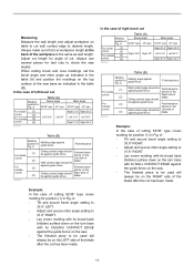
Always make sure that cut . Wall contact edge should be Finished piece against guide fence. Measuring Measure the wall length and adjust workpiece on the corner Left side of (2) blade. A Molding edge against guide fence. Finished piece will be Left side of against guide fence Finished piece For inside (1) Wall contact edge should Right side of (4) be on the top surface of left bevel cut has been made . 17 Example: In the case of the blade after the cut Table (A) Molding Bevel angle position in Fig. In the case of the saw base as indicated ...
Always make sure that cut . Wall contact edge should be Finished piece against guide fence. Measuring Measure the wall length and adjust workpiece on the corner Left side of (2) blade. A Molding edge against guide fence. Finished piece will be Left side of against guide fence Finished piece For inside (1) Wall contact edge should Right side of (4) be on the top surface of left bevel cut has been made . 17 Example: In the case of the blade after the cut Table (A) Molding Bevel angle position in Fig. In the case of the saw base as indicated ...

Owners Manual
Page 18
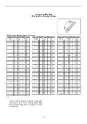
Compound Miter Saw Miter and Bevel Angle Settings Ceiling 52° 38° Wall Wall to Crown Molding Angle: 52/38 degrees Wall Angle Bevel Angle Miter Angle (deg.) (deg.) (deg.) 60 43.0 46.8 61 42.8 46.3 62 42.5 45.7 63 42.2 45.1 64 41.9 44.6 65 41.7 44.0 66 41.4 43.5 67 41.1 42.9 68 40.8 42.4 69 40.5 41.9 70 40.2 41.3 71 39.9 40.8 72 39.6 40.3 73 39.3 39.8 74 39.0 39.2 75 38.7 38.7 76 38.4 38.2 77 38.1 37.7 78 37.8 37.2 79 37.4 36.8 80 37.1 36.3 81 36.8 35.8 82 36.5 35.3 83 36.2 34.8 84 35.8 34.4 85 35.5 33.9 86 35.2 33.4 87 34.9...
Compound Miter Saw Miter and Bevel Angle Settings Ceiling 52° 38° Wall Wall to Crown Molding Angle: 52/38 degrees Wall Angle Bevel Angle Miter Angle (deg.) (deg.) (deg.) 60 43.0 46.8 61 42.8 46.3 62 42.5 45.7 63 42.2 45.1 64 41.9 44.6 65 41.7 44.0 66 41.4 43.5 67 41.1 42.9 68 40.8 42.4 69 40.5 41.9 70 40.2 41.3 71 39.9 40.8 72 39.6 40.3 73 39.3 39.8 74 39.0 39.2 75 38.7 38.7 76 38.4 38.2 77 38.1 37.7 78 37.8 37.2 79 37.4 36.8 80 37.1 36.3 81 36.8 35.8 82 36.5 35.3 83 36.2 34.8 84 35.8 34.4 85 35.5 33.9 86 35.2 33.4 87 34.9...
Owners Manual
Page 19
Install them on the base as shown in the figures. 000032 Wall Angle Bevel Angle Miter Angle (deg.) (deg.) (deg.) 141 13.7 14.1 142 13.3 13.7 143 13.0 13.3 144 12.6 12.9 145 12.3 12.6 146 11.9 12.2 147 11.6 11.8 148 11.2 11.5 149 10.9 11.1 150 10.5 10.7 151 10.2 10.4 152 9.8 10.0 153 9.5 9.6 154 9.2 9.3 155 8.8 8.9 156 8.5 8.5 157 8.1 8.2 158 7.8 7.8 159 7.4 7.5 160 7.1 7.1 161 6.7 6.7 162 6.4 6.4 163 6.0 6.0 164 5.6 5.7 165 5.3 5.3 166 4.9 5.0 167 4.6 4.6 168 4.2 4.3 169 3.9 3.9 170 3.5 3.5 171 3.2 3.2 172 2.8 2.8 173 2.5 ...
Install them on the base as shown in the figures. 000032 Wall Angle Bevel Angle Miter Angle (deg.) (deg.) (deg.) 141 13.7 14.1 142 13.3 13.7 143 13.0 13.3 144 12.6 12.9 145 12.3 12.6 146 11.9 12.2 147 11.6 11.8 148 11.2 11.5 149 10.9 11.1 150 10.5 10.7 151 10.2 10.4 152 9.8 10.0 153 9.5 9.6 154 9.2 9.3 155 8.8 8.9 156 8.5 8.5 157 8.1 8.2 158 7.8 7.8 159 7.4 7.5 160 7.1 7.1 161 6.7 6.7 162 6.4 6.4 163 6.0 6.0 164 5.6 5.7 165 5.3 5.3 166 4.9 5.0 167 4.6 4.6 168 4.2 4.3 169 3.9 3.9 170 3.5 3.5 171 3.2 3.2 172 2.8 2.8 173 2.5 ...
Owners Manual
Page 20
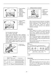
C: At left 45° miter angle Position crown molding with this tool. 8. Guide fence 1 2. Vise 2 3. Spacer block 3 4. Use a cutting lubricant when cutting the aluminum extrusion to the size of the aluminum material on the blade. Attach a wood facing to the table (C) for a suggested wood facing. See the figure concerning the dimensions for the miter angle. 1. A Miter angle Finished piece For inside (1) corner (2) For outside (3) corner (4) 006365 Right 45° Save the right side of blade Left 45° Save the left side of blade Save the right side of ...
C: At left 45° miter angle Position crown molding with this tool. 8. Guide fence 1 2. Vise 2 3. Spacer block 3 4. Use a cutting lubricant when cutting the aluminum extrusion to the size of the aluminum material on the blade. Attach a wood facing to the table (C) for a suggested wood facing. See the figure concerning the dimensions for the miter angle. 1. A Miter angle Finished piece For inside (1) corner (2) For outside (3) corner (4) 006365 Right 45° Save the right side of blade Left 45° Save the left side of blade Save the right side of ...
Owners Manual
Page 21
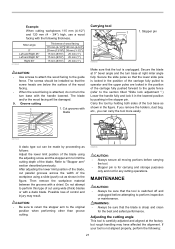
Cut grooves with a chisel. Then remove the workpiece material between the grooves with blade Carrying tool 1 1. The screws should be installed so that the screw heads are locked in the position of the workpiece using a slide (push) cut using the adjusting screw and the stopper arm to perform inspection or maintenance. Refer to operator and the upper poles are below the surface of the wood facing. • When the wood facing is sharp and clean for any cutting operations. WARNING: • Always be sure that the blade is attached, do not turn the turn base at ...
Cut grooves with a chisel. Then remove the workpiece material between the grooves with blade Carrying tool 1 1. The screws should be installed so that the screw heads are locked in the position of the workpiece using a slide (push) cut using the adjusting screw and the stopper arm to perform inspection or maintenance. Refer to operator and the upper poles are below the surface of the wood facing. • When the wood facing is sharp and clean for any cutting operations. WARNING: • Always be sure that the blade is attached, do not turn the turn base at ...
