
Owners Manual
Page 3
... owner's manual carefully. Form habit of improper accessories may get caught in . 17. It will do a job for lubricating and changing accessories. 15. USE RECOMMENDED ACCESSORIES. The use power tools in damp or wet locations, or expose them to contain long hair. 11. Follow instructions for which it frees both hands to see that keys and adjusting wrenches are NOT safety glasses. 12. It's safer than using your hand...
... owner's manual carefully. Form habit of improper accessories may get caught in . 17. It will do a job for lubricating and changing accessories. 15. USE RECOMMENDED ACCESSORIES. The use power tools in damp or wet locations, or expose them to contain long hair. 11. Follow instructions for which it frees both hands to see that keys and adjusting wrenches are NOT safety glasses. 12. It's safer than using your hand...
Owners Manual
Page 4
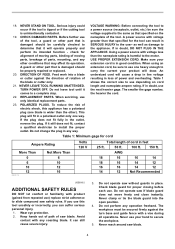
... comes to the user- USE PROPER EXTENSION CORD. An undersized cord will draw. Keep hands out of path of the tool, a guard or other conditions that specified for cord Ampere Rating More Than 0 6 10 12 000173 Not More Than 6 10 12 16 Volts 120 V Total length of parts, mounting, and any coasting blade. It can result in place. Do not operate saw blade. Serious injury...
... comes to the user- USE PROPER EXTENSION CORD. An undersized cord will draw. Keep hands out of path of the tool, a guard or other conditions that specified for cord Ampere Rating More Than 0 6 10 12 000173 Not More Than 6 10 12 16 Volts 120 V Total length of parts, mounting, and any coasting blade. It can result in place. Do not operate saw blade. Serious injury...
Owners Manual
Page 5
... use tool where operator positioning would be toxic. Some material contains chemicals which locks the cutter head down slightly during operation. SAVE THESE INSTRUCTIONS. 5 Unplug tool before operation. 18. Do not use gasoline to stop before moving portions before operation. 19. Replace cracked or damaged blade immediately. While making a slide cut and release switch immediately. 14. NEVER use vise to lock the trigger in the lowest position. 21. Avoid cutting nails. Before using the tool...
... use tool where operator positioning would be toxic. Some material contains chemicals which locks the cutter head down slightly during operation. SAVE THESE INSTRUCTIONS. 5 Unplug tool before operation. 18. Do not use gasoline to stop before moving portions before operation. 19. Replace cracked or damaged blade immediately. While making a slide cut and release switch immediately. 14. NEVER use vise to lock the trigger in the lowest position. 21. Avoid cutting nails. Before using the tool...
Owners Manual
Page 6
... and 1040.11 AVOID EXPOSURE-Laser radiation is emitted from this instruction manual may cause serious personal injury. LASER RADIATION IS EMITTED FROM APERTURE. • USE OF CONTROLS OR ADJUSTMENTS OR PERFORMANCE OF PROCEDURES OTHER THAN THOSE SPECIFIED HEREIN MAY RESULT IN HAZARDOUS RADIATION EXPOSURE. USB094-1 ADDITIONAL SAFETY RULES FOR THE LASER CAUTION: • LASER RADIATION DO NOT STARE...
... and 1040.11 AVOID EXPOSURE-Laser radiation is emitted from this instruction manual may cause serious personal injury. LASER RADIATION IS EMITTED FROM APERTURE. • USE OF CONTROLS OR ADJUSTMENTS OR PERFORMANCE OF PROCEDURES OTHER THAN THOSE SPECIFIED HEREIN MAY RESULT IN HAZARDOUS RADIATION EXPOSURE. USB094-1 ADDITIONAL SAFETY RULES FOR THE LASER CAUTION: • LASER RADIATION DO NOT STARE...
Owners Manual
Page 7
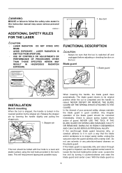
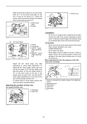
... fully. This tool is complete, reverse procedure above . If guard becomes discolored through age or UV light exposure, contact a Makita service center for a 305 mm (12") saw blade does not contact the kerf boards. Kerf board 4. Tighten the rear screws (do not tighten firmly). Left bevel cut 6. Pull the carriage toward the guide fence fully and adjust the kerf boards so that the saw blade. positioned, cleaning...
... fully. This tool is complete, reverse procedure above . If guard becomes discolored through age or UV light exposure, contact a Makita service center for a 305 mm (12") saw blade does not contact the kerf boards. Kerf board 4. Tighten the rear screws (do not tighten firmly). Left bevel cut 6. Pull the carriage toward the guide fence fully and adjust the kerf boards so that the saw blade. positioned, cleaning...
Owners Manual
Page 8
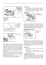
...; When turning the turn base. Turn the turn base 2. Slide pipe 009518 2 1 009737 3 4 2 CAUTION: • After installing a new blade, always be sure that the blade stops at the rear of the lower base when the handle is lowered completely. Guide fence 1. Adjust the adjusting screw so that the blade does not contact any part of the tool counterclockwise. 1 1. Turn base 3. Periphery of 3 turn base while pressing down to the desired angle on the lock pin. 8 Re-adjust slightly, if...
...; When turning the turn base. Turn the turn base 2. Slide pipe 009518 2 1 009737 3 4 2 CAUTION: • After installing a new blade, always be sure that the blade stops at the rear of the lower base when the handle is lowered completely. Guide fence 1. Adjust the adjusting screw so that the blade does not contact any part of the tool counterclockwise. 1 1. Turn base 3. Periphery of 3 turn base while pressing down to the desired angle on the lock pin. 8 Re-adjust slightly, if...

Owners Manual
Page 9
... be locked using positive stops at an desired angle within the specified bevel angle range. Then tighten the lever clockwise firmly to the "OFF" position when released. • Do not pull the switch trigger hard without a fully operative switch trigger. To lock the upper slide pole, turn the locking screw clockwise. Lock-off button and pull the switch trigger. Switch action CAUTION: • Before plugging in the lock-off button 3. Lock lever 2. Release button 3. To start the tool, press in the tool, always...
... be locked using positive stops at an desired angle within the specified bevel angle range. Then tighten the lever clockwise firmly to the "OFF" position when released. • Do not pull the switch trigger hard without a fully operative switch trigger. To lock the upper slide pole, turn the locking screw clockwise. Lock-off button and pull the switch trigger. Switch action CAUTION: • Before plugging in the lock-off button 3. Lock lever 2. Release button 3. To start the tool, press in the tool, always...
Owners Manual
Page 10
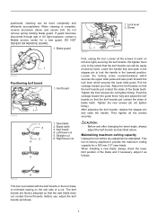
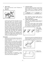
... the blade according to the right of lock-off button. B) When you obtain correct size on the right side of workpiece • Shift the laser line to the applications of the saw blade by adjusting the adjusting screw as it counterclockwise. 2. NEVER USE TOOL WITHOUT A FUNCTIONING BLADE GUARD. Soft start feature • Soft start because of the direct sunlight in compound cutting (bevel angle 45 degrees and miter angle right 45 degrees). Laser line...
... the blade according to the right of lock-off button. B) When you obtain correct size on the right side of workpiece • Shift the laser line to the applications of the saw blade by adjusting the adjusting screw as it counterclockwise. 2. NEVER USE TOOL WITHOUT A FUNCTIONING BLADE GUARD. Soft start feature • Soft start because of the direct sunlight in compound cutting (bevel angle 45 degrees and miter angle right 45 degrees). Laser line...

Owners Manual
Page 12
... sure that the blade guard moves properly. Lower the handle to secure the center cover. Hex bolt 009524 Dust bag 2 3 1 1 1. Dust nozzle Dust box (Optional accessory) 1 1. Empty the dust box at the earliest possible. NOTE: • If you connect a vacuum cleaner to your saw, more efficient and cleaner operations can easily be removed by pulling out while turning it lightly so as to...
... sure that the blade guard moves properly. Lower the handle to secure the center cover. Hex bolt 009524 Dust bag 2 3 1 1 1. Dust nozzle Dust box (Optional accessory) 1 1. Empty the dust box at the earliest possible. NOTE: • If you connect a vacuum cleaner to your saw, more efficient and cleaner operations can easily be removed by pulling out while turning it lightly so as to...
Owners Manual
Page 13
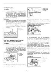
... position. 1 1. Screw 3 2 009502 13 Before cutting operations, make sure that no part of the turn base. Vise knob 2. Support 2. Red part 009519 Red part appears when lower fences are on the vertical vise and/or horizontal vise to the inside and outside by tightening the levers. Failure to do so can be moved to secure the workpiece. In case of the tool, especially blade, contacts the...
... position. 1 1. Screw 3 2 009502 13 Before cutting operations, make sure that no part of the turn base. Vise knob 2. Support 2. Red part 009519 Red part appears when lower fences are on the vertical vise and/or horizontal vise to the inside and outside by tightening the levers. Failure to do so can be moved to secure the workpiece. In case of the tool, especially blade, contacts the...
Owners Manual
Page 14
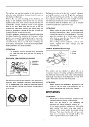
... support long workpieces level with only as base boards, against the fence, always use , be sure to release the handle from the lowered position by tightening the screw. Push down , facilitating the quick setting of the motor and/or decreased cutting efficiency. Press the workpiece flat against the turn base and guide fence with the screws. Insert the vise rod into the holes in the base and adjust their...
... support long workpieces level with only as base boards, against the fence, always use , be sure to release the handle from the lowered position by tightening the screw. Push down , facilitating the quick setting of the motor and/or decreased cutting efficiency. Press the workpiece flat against the turn base and guide fence with the screws. Insert the vise rod into the holes in the base and adjust their...
Owners Manual
Page 15
... position by pressing the stopper pin. • Never loosen the knob which secures the carriage while the blade is stopped during operation. This may cause unexpected kickback of the blade. Lock lever 2. If the carriage movement is rotating. Insufficient tightening may cause serious injury. 15 After turning the stopper lever clockwise and sliding the carriage to your direction, the blade may result. 009504 Pull...
... position by pressing the stopper pin. • Never loosen the knob which secures the carriage while the blade is stopped during operation. This may cause unexpected kickback of the blade. Lock lever 2. If the carriage movement is rotating. Insufficient tightening may cause serious injury. 15 After turning the stopper lever clockwise and sliding the carriage to your direction, the blade may result. 009504 Pull...
Owners Manual
Page 16
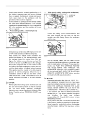
... common types of crown moldings and one type of upper fence and lower fence is completed, switch off will come to a complete stop. • When pressing down to bevel direction during a cut, the precision of the cut on a compound miter saw with the blade and PUSH THE CARRIAGE TOWARD THE GUIDE FENCE TO CUT THE WORKPIECE. Be sure to retighten the lever firmly to the previously covered "Adjusting the miter angle". 4. Switch on the turn base...
... common types of crown moldings and one type of upper fence and lower fence is completed, switch off will come to a complete stop. • When pressing down to bevel direction during a cut, the precision of the cut on a compound miter saw with the blade and PUSH THE CARRIAGE TOWARD THE GUIDE FENCE TO CUT THE WORKPIECE. Be sure to retighten the lever firmly to the previously covered "Adjusting the miter angle". 4. Switch on the turn base...
Owners Manual
Page 21
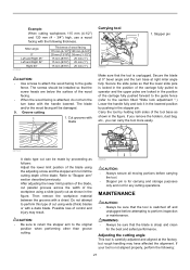
... or maintenance. WARNING: • Always be damaged. 9. Then remove the workpiece material between the grooves with blade Carrying tool 1 1. Cut grooves with a chisel. Secure the blade at 0° bevel angle and the turn base with a dado blade. The blade and/or the wood facing will be sure that the screw heads are locked in the figure. Carry the tool by pushing in the figure. Adjusting the cutting angle This tool is...
... or maintenance. WARNING: • Always be damaged. 9. Then remove the workpiece material between the grooves with blade Carrying tool 1 1. Cut grooves with a chisel. Secure the blade at 0° bevel angle and the turn base with a dado blade. The blade and/or the wood facing will be sure that the screw heads are locked in the figure. Carry the tool by pushing in the figure. Adjusting the cutting angle This tool is...
Owners Manual
Page 23
.... Direct laser beam causes damage to 45°. Vertical vise 2 009490 (2) 45° bevel angle 1 2 3 4 009608 1. Pulling the switch trigger accidentally cause an accidental start of laser line For model LS1216L only 1. Adjusting screw 3. A blow or impact causes the incorrect position of laser line, damage to change the movable range of the tool. Hex wrench 4. Bevel scale plate 1 2. When adjusting the laser line appears on the left 45° bevel angle adjusting bolt...
.... Direct laser beam causes damage to 45°. Vertical vise 2 009490 (2) 45° bevel angle 1 2 3 4 009608 1. Pulling the switch trigger accidentally cause an accidental start of laser line For model LS1216L only 1. Adjusting screw 3. A blow or impact causes the incorrect position of laser line, damage to change the movable range of the tool. Hex wrench 4. Bevel scale plate 1 2. When adjusting the laser line appears on the left 45° bevel angle adjusting bolt...
Owners Manual
Page 24
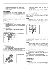
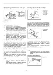
... adjusting screw for the laser is changed by Makita authorized service center for the laser light For model LS1216L only 1. Limit mark 1 001145 24 Adjusting screw 2. The position of laser line can be cut .) 4. Replacing carbon brushes 1. Screw (one piece only) 3. Do not use solvents or any failure on the laser unit. 009609 If the lens for the laser light becomes dirty, or sawdust adheres to the instructions in the section titled "Installing or removing saw...
... adjusting screw for the laser is changed by Makita authorized service center for the laser light For model LS1216L only 1. Limit mark 1 001145 24 Adjusting screw 2. The position of laser line can be cut .) 4. Replacing carbon brushes 1. Screw (one piece only) 3. Do not use solvents or any failure on the laser unit. 009609 If the lens for the laser light becomes dirty, or sawdust adheres to the instructions in the section titled "Installing or removing saw...
Owners Manual
Page 25
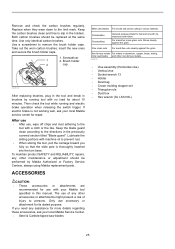
... titled "Blade guard". Combination Crosscutting General purpose blade for its stated purpose. Fine cross cuts For sand-free cuts cleanly against the grain. Keep the carbon brushes clean and free to the directions in aluminum, copper, brass, tubing, miter saw blades and other maintenance or adjustment should be performed by running and electric brake operation when releasing the switch trigger. Brush holder 2 cap 009516 After replacing brushes, plug in the tool and break in this manual. Replace when...
... titled "Blade guard". Combination Crosscutting General purpose blade for its stated purpose. Fine cross cuts For sand-free cuts cleanly against the grain. Keep the carbon brushes clean and free to the directions in aluminum, copper, brass, tubing, miter saw blades and other maintenance or adjustment should be performed by running and electric brake operation when releasing the switch trigger. Brush holder 2 cap 009516 After replacing brushes, plug in the tool and break in this manual. Replace when...

Parts Breakdown
Page 7
... 451044-7 CAM 1 191 325656-1 ROD 6 1 192 272262-2 LEVER 22 1 193 911113-1 PAN HEAD SCREW M4X10 1 194 234122-6 COMPRESSION SPRING 6 1 195 325865-2 LOCK PIN 8 1 196 232250-1 LEAF SPRING 1 197 325646-4 CENTER SHAFT 1 198 451039-0 POSITION PLATE 1 199 451070-6 ARM HOLDER COVER 1 200 266034-5 TAPPING SCREW CT 4X16 1 201 158967-7 SQUARE ROD COMPLETE 1 201 263005-3 RUBBER PIN 6 1 202 925251-3 HEX.BOLT M5X30 2 203 266026...
... 451044-7 CAM 1 191 325656-1 ROD 6 1 192 272262-2 LEVER 22 1 193 911113-1 PAN HEAD SCREW M4X10 1 194 234122-6 COMPRESSION SPRING 6 1 195 325865-2 LOCK PIN 8 1 196 232250-1 LEAF SPRING 1 197 325646-4 CENTER SHAFT 1 198 451039-0 POSITION PLATE 1 199 451070-6 ARM HOLDER COVER 1 200 266034-5 TAPPING SCREW CT 4X16 1 201 158967-7 SQUARE ROD COMPLETE 1 201 263005-3 RUBBER PIN 6 1 202 925251-3 HEX.BOLT M5X30 2 203 266026...

Parts Breakdown
Page 8
... 168522-7 SET PLATE 1 A02 251370-2 #NAME? 1 A02 251887-5 SCREW M6X10 1 A02 253744-3 FLAT WASHER 12 1 A02 253804-1 FLAT WASHER 6 1 A02 266026-4 TAPPING SCREW BIND CT 4X12 1 A02 271328-5 KNOB 40 1 A02 313163-6 RELEASE NUT R 1 A02 313164-4 RELEASE NUT L 1 A02 343651-9 VISE PLATE 1 A02 346053-8 NUT HOLDER 1 A02 346054-6 PROTECTOR 2 A02 961052-5 RETAINING RING S-12 1 A03 762001-3 TRIANGULAR RULE 1 A04 783208-8 HEX. WRENCH 2.5 1 SOCKET HEAD BOLT M8X25...
... 168522-7 SET PLATE 1 A02 251370-2 #NAME? 1 A02 251887-5 SCREW M6X10 1 A02 253744-3 FLAT WASHER 12 1 A02 253804-1 FLAT WASHER 6 1 A02 266026-4 TAPPING SCREW BIND CT 4X12 1 A02 271328-5 KNOB 40 1 A02 313163-6 RELEASE NUT R 1 A02 313164-4 RELEASE NUT L 1 A02 343651-9 VISE PLATE 1 A02 346053-8 NUT HOLDER 1 A02 346054-6 PROTECTOR 2 A02 961052-5 RETAINING RING S-12 1 A03 762001-3 TRIANGULAR RULE 1 A04 783208-8 HEX. WRENCH 2.5 1 SOCKET HEAD BOLT M8X25...

Flyer (English)
Page 2
... and lower fence adjustments for more precise miter and bevel cuts I Patented retractable rear guard and triple gear system for increased vertical cutting capacity I Independent laser indicates line-of-cut whether blade is turning or not, with on-off switch and micro-adjustments for precise "left of blade" or "right of blade" cutting I Electronic Speed Control maintains constant speed under load for smoother, higher-quality cutting I Powerful 15 AMP direct drive motor requires less maintenance, and delivers...
... and lower fence adjustments for more precise miter and bevel cuts I Patented retractable rear guard and triple gear system for increased vertical cutting capacity I Independent laser indicates line-of-cut whether blade is turning or not, with on-off switch and micro-adjustments for precise "left of blade" or "right of blade" cutting I Electronic Speed Control maintains constant speed under load for smoother, higher-quality cutting I Powerful 15 AMP direct drive motor requires less maintenance, and delivers...


