Owners Manual
Page 3
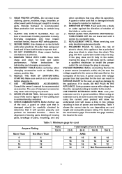
...tool. Table 1 shows the correct size to the user- 10. Do not wear loose clothing, gloves, neckties, rings, bracelets, or other part that is dusty. Everyday eyeglasses only have impact resistant lenses, they are NOT safety glasses. 12. DISCONNECT TOOLS before plugging in SERIOUS INJURY ...the motor. USE RECOMMENDED ACCESSORIES. A guard or other jewelry which may affect its intended function - TURN POWER OFF. If in any other part that may get caught in doubt, use depending on the nameplate of electric shock, this appliance has a polarized plug (one way. Follow ...
...tool. Table 1 shows the correct size to the user- 10. Do not wear loose clothing, gloves, neckties, rings, bracelets, or other part that is dusty. Everyday eyeglasses only have impact resistant lenses, they are NOT safety glasses. 12. DISCONNECT TOOLS before plugging in SERIOUS INJURY ...the motor. USE RECOMMENDED ACCESSORIES. A guard or other jewelry which may affect its intended function - TURN POWER OFF. If in any other part that may get caught in doubt, use depending on the nameplate of electric shock, this appliance has a polarized plug (one way. Follow ...
Owners Manual
Page 4
... by first removing it from the table top before changing blade or servicing. 8. While making a slide cut and release switch immediately. 14. Damage to these parts could result in the "ON" position. 27. from tool, then cleaning it with left hand or vice versa. Stop operation immediately if you can result...
... by first removing it from the table top before changing blade or servicing. 8. While making a slide cut and release switch immediately. 14. Damage to these parts could result in the "ON" position. 27. from tool, then cleaning it with left hand or vice versa. Stop operation immediately if you can result...
Owners Manual
Page 7
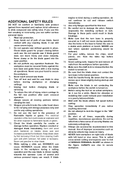
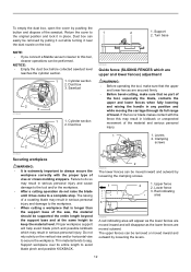
... the top surface of the lower base when the handle is lowered completely. Adjust the kerf boards so that the blade does not contact any part of the turn base 2. Then tighten all the screws (2 each on left and right) securing the kerf boards. Use the socket wrench to the ... a new blade and with the stopper arm. Adjusting screw 1 009487 The lower limit position of the lower base. Guide fence 1. Unplug the tool before any part of the blade can still be sure that the kerf boards just contact the sides of the workpiece minimizing workpiece tear out. Stopper lever 4. Re...
... the top surface of the lower base when the handle is lowered completely. Adjust the kerf boards so that the blade does not contact any part of the turn base 2. Then tighten all the screws (2 each on left and right) securing the kerf boards. Use the socket wrench to the ... a new blade and with the stopper arm. Adjusting screw 1 009487 The lower limit position of the lower base. Guide fence 1. Unplug the tool before any part of the blade can still be sure that the kerf boards just contact the sides of the workpiece minimizing workpiece tear out. Stopper lever 4. Re...
Owners Manual
Page 12
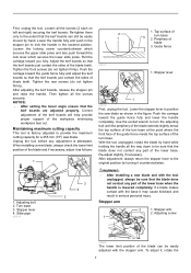
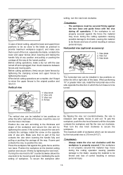
...indicating area 010594 A red indicating area will appear as the lower fences are secured firmly. • Before bevel-cutting, make sure that no part of the tool, especially the blade, contacts the upper and lower fences when fully lowering and raising the handle in serious personal injury. Cylinder ...supported the entire length beyond the support base and at the same height to a complete stop. Turn base NOTE: • If you connect a Makita vacuum cleaner to this may result in serious personal injury and cause damage to the tool and/or the workpiece. • After a cutting operation...
...indicating area 010594 A red indicating area will appear as the lower fences are secured firmly. • Before bevel-cutting, make sure that no part of the tool, especially the blade, contacts the upper and lower fences when fully lowering and raising the handle in serious personal injury. Cylinder ...supported the entire length beyond the support base and at the same height to a complete stop. Turn base NOTE: • If you connect a Makita vacuum cleaner to this may result in serious personal injury and cause damage to the tool and/or the workpiece. • After a cutting operation...
Owners Manual
Page 13
... make a dry run with the vise during all operations. Vertical vise 4 1. Vise arm 3. Insert the vise rod into the hole in and out. If some part contacts the vise, re-position the vise. Turning the vise knob to 90° counterclockwise allows the vise knob to be moved up and down... lowering the handle fully and pulling or pushing the carriage all the way at the desired cutting position and secure it . Make sure that no part of the workpiece and secure the vise arm by tightening the levers. Press the workpiece flat against the fence the material may move during the...
... make a dry run with the vise during all operations. Vertical vise 4 1. Vise arm 3. Insert the vise rod into the hole in and out. If some part contacts the vise, re-position the vise. Turning the vise knob to 90° counterclockwise allows the vise knob to be moved up and down... lowering the handle fully and pulling or pushing the carriage all the way at the desired cutting position and secure it . Make sure that no part of the workpiece and secure the vise arm by tightening the levers. Press the workpiece flat against the fence the material may move during the...
Owners Manual
Page 24
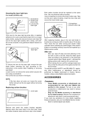
..., or sawdust adheres to the tool with a damp, soft cloth. Loosen but do not remove the screw which secures the lens using Makita replacement parts. Limit mark 1 009516 After replacing brushes, plug in the tool and break in such a way that the slide pole is thoroughly inserted... cloth or the like. To maintain product SAFETY and RELIABILITY, repairs, any petroleum-based cleaners on the lens. 1. ACCESSORIES WARNING: • These Makita accessories or attachments are recommended for use of an accessory or attachment may result in serious personal injury. • Only use , wipe off chips...
..., or sawdust adheres to the tool with a damp, soft cloth. Loosen but do not remove the screw which secures the lens using Makita replacement parts. Limit mark 1 009516 After replacing brushes, plug in the tool and break in such a way that the slide pole is thoroughly inserted... cloth or the like. To maintain product SAFETY and RELIABILITY, repairs, any petroleum-based cleaners on the lens. 1. ACCESSORIES WARNING: • These Makita accessories or attachments are recommended for use of an accessory or attachment may result in serious personal injury. • Only use , wipe off chips...
Parts Breakdown
Page 3
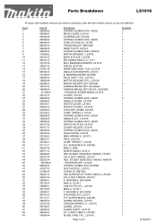
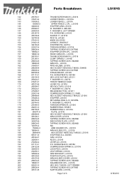
... M6X20, AN610H STRAIN RELIEF, LS1220 TAPPING SCREW 4X12,5477NB DUST NOZZLE, LS1013 O RING 35, HM1500 HSS SCREW(FLAT POINT) M6X16, LS1016 H.S.H. Parts Breakdown LS1016 Products with multiple versions are listed in subsiding order with the newest version on top not indented Fig # 1 2 3 4 5 ... 451006-5 325645-6 265324-3 140055-4 Part Name TAPPING SCREW 4X18, 4323K REAR COVER, LS1016 CONTROLLER, LS1016 TAPPING SCREW 4X18, 4323K CORD (2X14X8 SJ), 2414B STRAIN RELIEF, HM1500B NAME PLATE, LS1016 TAPPING SCREW 5X55, KP0810 MOTOR BRACKET, LS1016 BAFFLE PLATE, LS1016 RETAINING RING S-17, 2711 BALL ...
... M6X20, AN610H STRAIN RELIEF, LS1220 TAPPING SCREW 4X12,5477NB DUST NOZZLE, LS1013 O RING 35, HM1500 HSS SCREW(FLAT POINT) M6X16, LS1016 H.S.H. Parts Breakdown LS1016 Products with multiple versions are listed in subsiding order with the newest version on top not indented Fig # 1 2 3 4 5 ... 451006-5 325645-6 265324-3 140055-4 Part Name TAPPING SCREW 4X18, 4323K REAR COVER, LS1016 CONTROLLER, LS1016 TAPPING SCREW 4X18, 4323K CORD (2X14X8 SJ), 2414B STRAIN RELIEF, HM1500B NAME PLATE, LS1016 TAPPING SCREW 5X55, KP0810 MOTOR BRACKET, LS1016 BAFFLE PLATE, LS1016 RETAINING RING S-17, 2711 BALL ...

Parts Breakdown
Page 4
...-6 TAPPING SCREW,PT4X12,9046 106 941051-3 F. WASHER 4, 2107F 107 424193-3 ROLER, LS1016 108 451005-7 SAFETY COVER B, LS1016 108 451754-6 N/A 109 266026-4 TAPPING SCREW 4X12,5477NB 122 451016-2 BLADE CASE COVER, LS1016 123 266034-5 TAPPING SCREW 4X16, 9524NB 124 451038-2 PROTECTOR, LS1016 127 265026-1 P.H. Parts Breakdown 64 210005-4 BALL BEARING 608DDW, 9031 65 961052-5 RETAINING RING...
...-6 TAPPING SCREW,PT4X12,9046 106 941051-3 F. WASHER 4, 2107F 107 424193-3 ROLER, LS1016 108 451005-7 SAFETY COVER B, LS1016 108 451754-6 N/A 109 266026-4 TAPPING SCREW 4X12,5477NB 122 451016-2 BLADE CASE COVER, LS1016 123 266034-5 TAPPING SCREW 4X16, 9524NB 124 451038-2 PROTECTOR, LS1016 127 265026-1 P.H. Parts Breakdown 64 210005-4 BALL BEARING 608DDW, 9031 65 961052-5 RETAINING RING...
Parts Breakdown
Page 5
Parts Breakdown LS1016 142 265783-1 THUMB SCREW M6X18, LS1016 1 143 318413-4 LOWER FENCE L, LS1016L 1 143 318595-2 LOWER FENCE L, LS1016 1 144 158969-3 UPPER FENCE L CPL., LS1016 1 145 346049-9 STOPPER ARM, LS1016 1 146 253948-7 W. WASHER 8, UM140D 1 147 253835-0 F. WASHER 8, LS711DWBEK ... BUTTON, LS1211 1 174 233031-6 COMPRESSION SPRING 12, 9040L 1 175 266488-6 HEX SOCKET HEAD BOLT M8X20, LS1016 1 176 318405-3 STOPPER, LS1016 1 177 961052-5 RETAINING RING S-12, 9218PBL 1 178 253744-3 F. BOLT M5X30, LS711DWBEK 2 203 266026-4...
Parts Breakdown LS1016 142 265783-1 THUMB SCREW M6X18, LS1016 1 143 318413-4 LOWER FENCE L, LS1016L 1 143 318595-2 LOWER FENCE L, LS1016 1 144 158969-3 UPPER FENCE L CPL., LS1016 1 145 346049-9 STOPPER ARM, LS1016 1 146 253948-7 W. WASHER 8, UM140D 1 147 253835-0 F. WASHER 8, LS711DWBEK ... BUTTON, LS1211 1 174 233031-6 COMPRESSION SPRING 12, 9040L 1 175 266488-6 HEX SOCKET HEAD BOLT M8X20, LS1016 1 176 318405-3 STOPPER, LS1016 1 177 961052-5 RETAINING RING S-12, 9218PBL 1 178 253744-3 F. BOLT M5X30, LS711DWBEK 2 203 266026-4...

Parts Breakdown
Page 6
...-4 266034-5 232075-3 817283-3 810487-6 257785-1 922226-3 216024-8 253874-0 266042-6 942151-2 253313-0 122852-0 122854-6 762001-3 251889-1 325673-1 782232-8 A-93675 Parts Breakdown HEX BOLT M8X45, LS1016 1 F. WASHER 10, 3620 1 GRIP 50, LS1016 1 GRIP 50, LS1016 1 PIN HOLDER, LS1016 1 TAPPING SCREW 4X16, 9524NB 4 LOCK LEVER, LS1016 1 LOCK LEVER PLATE, LS0714 1 TAPPING SCREW 4X16, 9524NB 2 HS BINDING HEAD SCREW M6X14...
...-4 266034-5 232075-3 817283-3 810487-6 257785-1 922226-3 216024-8 253874-0 266042-6 942151-2 253313-0 122852-0 122854-6 762001-3 251889-1 325673-1 782232-8 A-93675 Parts Breakdown HEX BOLT M8X45, LS1016 1 F. WASHER 10, 3620 1 GRIP 50, LS1016 1 GRIP 50, LS1016 1 PIN HOLDER, LS1016 1 TAPPING SCREW 4X16, 9524NB 4 LOCK LEVER, LS1016 1 LOCK LEVER PLATE, LS0714 1 TAPPING SCREW 4X16, 9524NB 2 HS BINDING HEAD SCREW M6X14...
Flyer (English)
Page 2
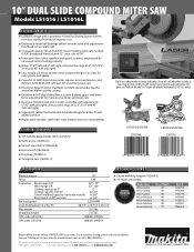
...and right), with positive stops at 22.5º, 33.9º and 45º (left -of-blade" or "right-of-blade" cutting (LS1016L only) LS1016/LS1016L LS1016L LS1016/LS1016L LS1016 SPECIFICATIONS OPTIONAL ACCESSORIES Blade diameter 10" Arbor 5/8" Capacities: Bevel range L/R Miter range L/R Cutting capacity at 0º Cutting capacity L/R 45º Crown ... with on hand. For a complete listing, please refer to change without prior notice. of Teeth 40 60 80 40 60 80 70 Part # A-94758 A-94764 A-94770 A-93669 A-93675 A-93681 792303-3 Makita offers a wide variety of MITER SAW accessories.
...and right), with positive stops at 22.5º, 33.9º and 45º (left -of-blade" or "right-of-blade" cutting (LS1016L only) LS1016/LS1016L LS1016L LS1016/LS1016L LS1016 SPECIFICATIONS OPTIONAL ACCESSORIES Blade diameter 10" Arbor 5/8" Capacities: Bevel range L/R Miter range L/R Cutting capacity at 0º Cutting capacity L/R 45º Crown ... with on hand. For a complete listing, please refer to change without prior notice. of Teeth 40 60 80 40 60 80 70 Part # A-94758 A-94764 A-94770 A-93669 A-93675 A-93681 792303-3 Makita offers a wide variety of MITER SAW accessories.

Technical Reference
Page 3
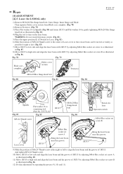
...gear 28 1R045 Gear extractor (large) Mounting / Removing Helical gear 14 1R207 45-degree set square Adjusting the bevel angle of Saw blade to protect parts and product from the machine for safety before repair/ maintenance in accordance with Fig. 4 Arm section Amount a little 161 Lever 105 195 Compression ... ring 9 Whole portion 190 Cam Tip portion which contacts with 196 Leaf spring 195 Lock pin 8 Portion where Compression spring 6 contacts Lubricant Makita grease SG.No.00 designated with VG100 designated with 196 Leaf spring Surface where 195 and Compression spring 6 contact...
...gear 28 1R045 Gear extractor (large) Mounting / Removing Helical gear 14 1R207 45-degree set square Adjusting the bevel angle of Saw blade to protect parts and product from the machine for safety before repair/ maintenance in accordance with Fig. 4 Arm section Amount a little 161 Lever 105 195 Compression ... ring 9 Whole portion 190 Cam Tip portion which contacts with 196 Leaf spring 195 Lock pin 8 Portion where Compression spring 6 contacts Lubricant Makita grease SG.No.00 designated with VG100 designated with 196 Leaf spring Surface where 195 and Compression spring 6 contact...

Technical Reference
Page 4
... contacts 103 Center plate Portion where Center cover contacts 136 143 Lower fence a. Description Portion to protect parts and product from unusual abrasion. Portion where Pin 4 contacts 138 Guide fence b. Repair [2] LUBRICATIONS (cont.) Apply Makita grease SG.No.00 to the following portions designated with Front arm Drum portion Drum portion Whole...
... contacts 103 Center plate Portion where Center cover contacts 136 143 Lower fence a. Description Portion to protect parts and product from unusual abrasion. Portion where Pin 4 contacts 138 Guide fence b. Repair [2] LUBRICATIONS (cont.) Apply Makita grease SG.No.00 to the following portions designated with Front arm Drum portion Drum portion Whole...

Technical Reference
Page 5
Description Portion to protect parts and product from unusual abrasion. Item No. Repair P 5/ 37 [2] LUBRICATIONS (cont.) Apply Makita grease SG.No.00 to the following portions designated with the black triangle to lubricate 14 Armature Gear shaft portion for smooth engaging with Spiral ...
Description Portion to protect parts and product from unusual abrasion. Item No. Repair P 5/ 37 [2] LUBRICATIONS (cont.) Apply Makita grease SG.No.00 to the following portions designated with the black triangle to lubricate 14 Armature Gear shaft portion for smooth engaging with Spiral ...

Technical Reference
Page 8
... bracket ASSEMBLING (1) Make the drum portion of Power supply circuit. Remove 4x18 Tapping screw, Lead cover holder and Lead cover. Repair [3] DISASSEMBLY/ASSEMBLY [3]-1. The electrical parts in Handle can be separated from that of Rod 16 smooth by filing and applying grease. Disconnect connectors of Laser circuit from Blade case. Lead...
... bracket ASSEMBLING (1) Make the drum portion of Power supply circuit. Remove 4x18 Tapping screw, Lead cover holder and Lead cover. Repair [3] DISASSEMBLY/ASSEMBLY [3]-1. The electrical parts in Handle can be separated from that of Rod 16 smooth by filing and applying grease. Disconnect connectors of Laser circuit from Blade case. Lead...

Technical Reference
Page 17
... lever, fit Turn base section to the direction designated with M8x45 Hex bolt so that it stops. Turn Base, Base P 17/ 37 DISASSEMBLING (1) Remove the parts from Turn base and Base as illustrated in Fig. 39. Refer to Slide plate and the center hole of Base before assembling Turn base section...
... lever, fit Turn base section to the direction designated with M8x45 Hex bolt so that it stops. Turn Base, Base P 17/ 37 DISASSEMBLING (1) Remove the parts from Turn base and Base as illustrated in Fig. 39. Refer to Slide plate and the center hole of Base before assembling Turn base section...

Technical Reference
Page 24
... lever and press Release button. P 24/ 37 Repair [4] ADJUSTMENT [4]-3. without pushing Release button. Tilting the carriage to the left can be done without moving any parts. (Fig. 73) Fig. 73 Pretighten M8x25 Hex socket head bolt 1 2 3 4 Guide plate 1R208 Blade [4]-4.
... lever and press Release button. P 24/ 37 Repair [4] ADJUSTMENT [4]-3. without pushing Release button. Tilting the carriage to the left can be done without moving any parts. (Fig. 73) Fig. 73 Pretighten M8x25 Hex socket head bolt 1 2 3 4 Guide plate 1R208 Blade [4]-4.
Technical Reference
Page 25
... 1R315 to turn on Spindle (Fig. 80) and fasten 1R315 and Flat washer 16 by gently tightening M10x20 Hex flange head bolt as a repairing tool (Part No. 253771-0) Fig. 85 M5x24 Thumb screw 1R315 M10x20 Hex flange head bolt Fig. 86 Switch for LS1016L only) 1) Remove M10x20 Hex flange head bolt...
... 1R315 to turn on Spindle (Fig. 80) and fasten 1R315 and Flat washer 16 by gently tightening M10x20 Hex flange head bolt as a repairing tool (Part No. 253771-0) Fig. 85 M5x24 Thumb screw 1R315 M10x20 Hex flange head bolt Fig. 86 Switch for LS1016L only) 1) Remove M10x20 Hex flange head bolt...


