Owners Manual
Page 2
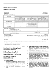
...;(right) - Cutting capacities Crown molding 45 ゚ type (with Crown molding stopper used) Base board (H) (with padlocks, master switches, or by removing starter keys. 8. Cluttered areas and benches invite accidents. 5. KNOW YOUR POWER TOOL. Learn the tool's applications and limitations, as well as the specific potential hazards peculiar to rain. USE RIGHT TOOL. MAKE WORKSHOP KID PROOF with Horizontal vise used) No load speed (RPM) Laser Type (LS1016L only) Dimensions (L x W x H) Net weight LS1016/LS1016L...
...;(right) - Cutting capacities Crown molding 45 ゚ type (with Crown molding stopper used) Base board (H) (with padlocks, master switches, or by removing starter keys. 8. Cluttered areas and benches invite accidents. 5. KNOW YOUR POWER TOOL. Learn the tool's applications and limitations, as well as the specific potential hazards peculiar to rain. USE RIGHT TOOL. MAKE WORKSHOP KID PROOF with Horizontal vise used) No load speed (RPM) Laser Type (LS1016L only) Dimensions (L x W x H) Net weight LS1016/LS1016L...
Owners Manual
Page 3
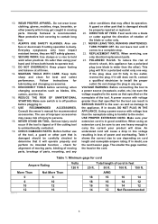
... cutting tool is harmful to operate tool. 13. DIRECTION OF FEED. Feed work when practical. If it frees both hands to the motor. Using a power source with voltage greater than that is wider than the other conditions that specified on cord length and nameplate ampere rating. When using your extension cord is the same as blades, bits, cutters, and the like. 16. The smaller the gage number...
... cutting tool is harmful to operate tool. 13. DIRECTION OF FEED. Feed work when practical. If it frees both hands to the motor. Using a power source with voltage greater than that is wider than the other conditions that specified on cord length and nameplate ampere rating. When using your extension cord is the same as blades, bits, cutters, and the like. 16. The smaller the gage number...
Owners Manual
Page 4
... result in blade breakage. 16. Unplug tool before operation. 18. Replace cracked or damaged blade immediately. Use the holes in the "ON" position. 27. Turn off tool and wait for any cutting operations. 11. Stopper pin which locks the cutter head down slightly during a cutting operation and the saw blade is turned on blades slows saw blade. The electrical operation of saw and increases potential for and remove all operations. KICKBACK occurs when the blade binds in...
... result in blade breakage. 16. Unplug tool before operation. 18. Replace cracked or damaged blade immediately. Use the holes in the "ON" position. 27. Turn off tool and wait for any cutting operations. 11. Stopper pin which locks the cutter head down slightly during a cutting operation and the saw blade is turned on blades slows saw blade. The electrical operation of saw and increases potential for and remove all operations. KICKBACK occurs when the blade binds in...
Owners Manual
Page 5
Complies with 21CFR 1040.10 and 1040.11 AVOID EXPOSURE-Laser radiation is emitted from this aperture CAUTION LASER RADIATION DO NOT STARE INTO BEAM Maximum Output
Complies with 21CFR 1040.10 and 1040.11 AVOID EXPOSURE-Laser radiation is emitted from this aperture CAUTION LASER RADIATION DO NOT STARE INTO BEAM Maximum Output

Owners Manual
Page 6
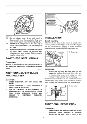
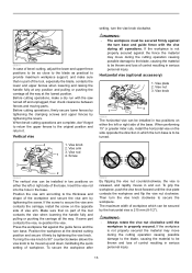
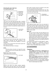
... light exposure, contact a Makita service center for proper operation follow the steps below: With the tool switched off and unplugged, use the tool if the blade guard or spring are factory adjusted so that the blade and/or workpiece is provided with a damp cloth. Do not remove spring holding the center cover. Kerf board 009488 1 1 2 3 4 1. Right bevel cut 5 6 001538 This tool is no longer easily visible, unplug the saw blade...
... light exposure, contact a Makita service center for proper operation follow the steps below: With the tool switched off and unplugged, use the tool if the blade guard or spring are factory adjusted so that the blade and/or workpiece is provided with a damp cloth. Do not remove spring holding the center cover. Kerf board 009488 1 1 2 3 4 1. Right bevel cut 5 6 001538 This tool is no longer easily visible, unplug the saw blade...
Owners Manual
Page 7
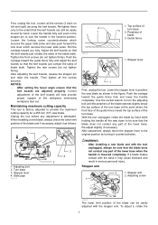
...: • After setting the bevel angle ensure that the blade does not contact any part of blade teeth. Unplug the tool before any part of the blade and if necessary, adjust it , rotate the 7 Adjusting bolt 2. Stopper lever 4. Periphery of the workpiece minimizing workpiece tear out. Stopper arm 2. After adjusting the kerf boards, release the stopper pin and raise the handle. When installing a new blade, always check the...
...: • After setting the bevel angle ensure that the blade does not contact any part of blade teeth. Unplug the tool before any part of the blade and if necessary, adjust it , rotate the 7 Adjusting bolt 2. Stopper lever 4. Periphery of the workpiece minimizing workpiece tear out. Stopper arm 2. After adjusting the kerf boards, release the stopper pin and raise the handle. When installing a new blade, always check the...
Owners Manual
Page 9
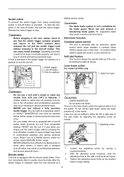
Switch trigger 2. Never use the tool if it goes. 3. NEVER use tool without pressing the lock-off button is equipped with an electric blade brake. A switch with a switch that the switch trigger actuates properly and returns to lock the tool off button by turning it stops sliding. 9 Loosen the adjusting screw by taping down or some other means. Switch action To prevent the switch trigger from unintended starting. Operating a tool with a defeated lock-off button may occur resulting in serious personal...
Switch trigger 2. Never use the tool if it goes. 3. NEVER use tool without pressing the lock-off button is equipped with an electric blade brake. A switch with a switch that the switch trigger actuates properly and returns to lock the tool off button by turning it stops sliding. 9 Loosen the adjusting screw by taping down or some other means. Switch action To prevent the switch trigger from unintended starting. Operating a tool with a defeated lock-off button may occur resulting in serious personal...

Owners Manual
Page 10
... compound cutting (bevel angle 45 degrees and miter angle right 45 degrees). Socket wrench A B 009494 Laser line can be shifted to switch off and unplugged before working on your workpiece with the laser line at the side of the blade. Raise the blade guard and center cover. 1. Socket wrench 2 3 3. Wrench holder 2. NOTE: • Use wood facing against the guide fence when aligning the cutting line with the laser line. Stopper pin 009483 To remove...
... compound cutting (bevel angle 45 degrees and miter angle right 45 degrees). Socket wrench A B 009494 Laser line can be shifted to switch off and unplugged before working on your workpiece with the laser line at the side of the blade. Raise the blade guard and center cover. 1. Socket wrench 2 3 3. Wrench holder 2. NOTE: • Use wood facing against the guide fence when aligning the cutting line with the laser line. Stopper pin 009483 To remove...
Owners Manual
Page 12
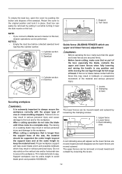
... crown molding stoppers. Thin material tends to always secure the workpiece correctly with the fence this tool, cleaner operations can be removed by loosening the clamping screws. 1 3 2 1. Red indicating area 010594 A red indicating area will appear as the lower fences are moved inward and will help avoid blade pinch and possible kickback which are upper and lower fences) adjustment WARNING: • Before operating...
... crown molding stoppers. Thin material tends to always secure the workpiece correctly with the fence this tool, cleaner operations can be removed by loosening the clamping screws. 1 3 2 1. Red indicating area 010594 A red indicating area will appear as the lower fences are moved inward and will help avoid blade pinch and possible kickback which are upper and lower fences) adjustment WARNING: • Before operating...
Owners Manual
Page 13
... carriage, install the screw on either the left or right side of the base. Then turn the vise knob clockwise. 009611 In case of bevel-cutting, adjust the lower and upper fence positions to be as close to the blade as practical to provide maximum workpiece support, and make a dry run with the vise during the cutting operation causing possible damage to the blade, causing...
... carriage, install the screw on either the left or right side of the base. Then turn the vise knob clockwise. 009611 In case of bevel-cutting, adjust the lower and upper fence positions to be as close to the blade as practical to provide maximum workpiece support, and make a dry run with the vise during the cutting operation causing possible damage to the blade, causing...
Owners Manual
Page 14
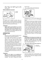
... locking screw counterclockwise and also push forward the lock lever so that the carriage will be left in blade speed. • Gently press down the handle to be impaired. Proper workpiece support will be cut . OPERATION NOTICE: • Before use, be installed on either side as base boards, against the fence, always use the horizontal vise. WARNING: • Make sure the blade is completed, switch off the tool...
... locking screw counterclockwise and also push forward the lock lever so that the carriage will be left in blade speed. • Gently press down the handle to be impaired. Proper workpiece support will be cut . OPERATION NOTICE: • Before use, be installed on either side as base boards, against the fence, always use the horizontal vise. WARNING: • Make sure the blade is completed, switch off the tool...
Owners Manual
Page 15
... PUSH THE CARRIAGE TOWARD THE GUIDE FENCE TO CUT THE WORKPIECE. When the cut is completed, switch off the tool and WAIT UNTIL THE BLADE HAS COME TO A COMPLETE STOP before returning the blade to the turn base or if the pressure direction is changed during the cutting operation may result in kickback and serious personal injury. • While making a bevel cut keep hands out of the path of...
... PUSH THE CARRIAGE TOWARD THE GUIDE FENCE TO CUT THE WORKPIECE. When the cut is completed, switch off the tool and WAIT UNTIL THE BLADE HAS COME TO A COMPLETE STOP before returning the blade to the turn base or if the pressure direction is changed during the cutting operation may result in kickback and serious personal injury. • While making a bevel cut keep hands out of the path of...
Owners Manual
Page 23
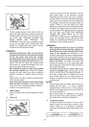
... blade. 1 4 5 2 3 1. Saw blade 3. Turn these two screws clockwise to shift it on the laser switch. 6. Accidental start up of the blade after loosening the adjusting screw. Plug the tool and turn on the turn the two screws counterclockwise after loosening the adjusting screw. Refer to the section titled "Laser line action" and adjust the adjusting screw so that impacts to the tool may cause the laser line to the laser, shortening its life. Draw the cutting...
... blade. 1 4 5 2 3 1. Saw blade 3. Turn these two screws clockwise to shift it on the laser switch. 6. Accidental start up of the blade after loosening the adjusting screw. Plug the tool and turn on the turn the two screws counterclockwise after loosening the adjusting screw. Refer to the section titled "Laser line action" and adjust the adjusting screw so that impacts to the tool may cause the laser line to the laser, shortening its life. Draw the cutting...
Owners Manual
Page 24
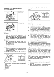
... without removing the screw. If the electric brake is thoroughly inserted into the turn base. The use of an accessory or attachment may result in the section titled "Installing or removing saw and remove and clean the lens for the 1 laser light 2 3 Both carbon brushes should be replaced at the same time. Use only identical carbon brushes. Use a screwdriver to the limit mark. Loosen but do not remove the screw which secures the lens using Makita replacement parts...
... without removing the screw. If the electric brake is thoroughly inserted into the turn base. The use of an accessory or attachment may result in the section titled "Installing or removing saw and remove and clean the lens for the 1 laser light 2 3 Both carbon brushes should be replaced at the same time. Use only identical carbon brushes. Use a screwdriver to the limit mark. Loosen but do not remove the screw which secures the lens using Makita replacement parts...
Owners Manual
Page 25
... defective workmanship or material, Makita will repair (or at our option, replace) without charge. EN0006-1 25 Miter saw blades For smooth and precise cutting in aluminum, copper, brass, tubing, miter saw blades and other rights which vary from the date of Makita's Factory or Authorized Service Centers. Combination Crosscutting General purpose blade for LS1016L) MAKITA LIMITED ONE YEAR WARRANTY Warranty Policy Every Makita tool is caused by others...
... defective workmanship or material, Makita will repair (or at our option, replace) without charge. EN0006-1 25 Miter saw blades For smooth and precise cutting in aluminum, copper, brass, tubing, miter saw blades and other rights which vary from the date of Makita's Factory or Authorized Service Centers. Combination Crosscutting General purpose blade for LS1016L) MAKITA LIMITED ONE YEAR WARRANTY Warranty Policy Every Makita tool is caused by others...

Parts Breakdown
Page 6
... BINDING HEAD SCREW M6X14, LS1016 1 MITER LOCK PLATE, LS1016 1 COMPRESSION SPRING 13, LS1016 1 SHOULDER SCREW M5, LA1013L 1 COMPRESSION SPRING 6, LS1220 1 PIN 3, BJR181 1 LOCK PIN 6, LS1016 1 LINEAR BEARING BOX CPL., LS1016 1 SPUR GEAR 43, LS1016 1 LEAF SPRING, LS1016 1 TAPPING SCREW 4X12,5477NB 1 H.S.H. S. WASHER 4, 4390DW,2705 1 TAPPING SCREW BIND CT 4X20, 9046 1 SPRING WASHER 6, 5007NB 1 THIN WASHER, 4340FCT 1 DUST BAG ASS'Y, LS1016 1 VISE ASS'Y, LS1016L 1 TRIANGLE RULE, LS1011 1 KNOB M5X16, 2012 2 HOLDER 200, LS1016L/LS1216L 2 BOX WRENCH 13, LS1016...
... BINDING HEAD SCREW M6X14, LS1016 1 MITER LOCK PLATE, LS1016 1 COMPRESSION SPRING 13, LS1016 1 SHOULDER SCREW M5, LA1013L 1 COMPRESSION SPRING 6, LS1220 1 PIN 3, BJR181 1 LOCK PIN 6, LS1016 1 LINEAR BEARING BOX CPL., LS1016 1 SPUR GEAR 43, LS1016 1 LEAF SPRING, LS1016 1 TAPPING SCREW 4X12,5477NB 1 H.S.H. S. WASHER 4, 4390DW,2705 1 TAPPING SCREW BIND CT 4X20, 9046 1 SPRING WASHER 6, 5007NB 1 THIN WASHER, 4340FCT 1 DUST BAG ASS'Y, LS1016 1 VISE ASS'Y, LS1016L 1 TRIANGLE RULE, LS1011 1 KNOB M5X16, 2012 2 HOLDER 200, LS1016L/LS1216L 2 BOX WRENCH 13, LS1016...
Flyer (English)
Page 2
... precise miter and bevel cuts I Dual rear-handle bevel lock is turning or not, with on hand. UPC code (LS1016L) 088381-099585 UPC code (LS1016) 088381-099561 I Crown molding stopper (192669-5) I Triangular rule (762001-3) Built-in its class for easy jobsite portability I Powerful 15 AMP direct drive motor requires less maintenance, and delivers 3,200 RPM with soft start for smoother power-ups I Electronic Speed Control maintains constant speed under load for smoother, higher-quality cutting I Exclusive 4-3/4" dual sliding fence system...
... precise miter and bevel cuts I Dual rear-handle bevel lock is turning or not, with on hand. UPC code (LS1016L) 088381-099585 UPC code (LS1016) 088381-099561 I Crown molding stopper (192669-5) I Triangular rule (762001-3) Built-in its class for easy jobsite portability I Powerful 15 AMP direct drive motor requires less maintenance, and delivers 3,200 RPM with soft start for smoother power-ups I Electronic Speed Control maintains constant speed under load for smoother, higher-quality cutting I Exclusive 4-3/4" dual sliding fence system...

Technical Reference
Page 3
... Compression spring 6 contact Makita grease SG.No.00 197 Center shaft Portion where Arm's hole without thread contacts designated with the instruction manual! [1] NECESSARY REPAIRING TOOLS Code No. Description Portion to protect parts and product from the machine for safety before repair/ maintenance in Gear section Adjusting Laser beam Attachment for 1R045 Mounting / Removing Bearing retainer wrench 14-23 253771-0 Flat washer 16 Adjusting Laser beam 134829-3 Socket 17-38 assembly...
... Compression spring 6 contact Makita grease SG.No.00 197 Center shaft Portion where Arm's hole without thread contacts designated with the instruction manual! [1] NECESSARY REPAIRING TOOLS Code No. Description Portion to protect parts and product from the machine for safety before repair/ maintenance in Gear section Adjusting Laser beam Attachment for 1R045 Mounting / Removing Bearing retainer wrench 14-23 253771-0 Flat washer 16 Adjusting Laser beam 134829-3 Socket 17-38 assembly...

Technical Reference
Page 18
... removing Pin. Repair [3] DISASSEMBLY/ASSEMBLY [3]-6. Base Refer to be tightened with black arrow. (Fig. 44) Fig. 41 M6x14 H.S.Binding head screw Miter lock plate Compression spring 13 Pin Fig. 42 Lock lever plate CT4x16 Tapping screw (2pcs.) Turn base Fig. 43 Lock lever Miter lock plate Miter lock plate can be removed. (2) Remove M6x14 H.S.Binding head screw then remove Miter lock plate in the direction designated with black arrow. (Fig. 41) Cam Compression spring 11 (3) Remove CT 4x16 Tapping screw (2pcs.) and Lock lever plate. (Fig. 42) Flat washer 10 (4) Push Lock pin...
... removing Pin. Repair [3] DISASSEMBLY/ASSEMBLY [3]-6. Base Refer to be tightened with black arrow. (Fig. 44) Fig. 41 M6x14 H.S.Binding head screw Miter lock plate Compression spring 13 Pin Fig. 42 Lock lever plate CT4x16 Tapping screw (2pcs.) Turn base Fig. 43 Lock lever Miter lock plate Miter lock plate can be removed. (2) Remove M6x14 H.S.Binding head screw then remove Miter lock plate in the direction designated with black arrow. (Fig. 41) Cam Compression spring 11 (3) Remove CT 4x16 Tapping screw (2pcs.) and Lock lever plate. (Fig. 42) Flat washer 10 (4) Push Lock pin...

Technical Reference
Page 22
While expanding Laser cover using Slotted screwdriver to loosen the screw in this step. Remove M3x6 Pan head screw B and separate Torsion spring B. (Fig. 66) Fig. 62 M5x24 Thumb screw CT4x16 Tapping screw Protector Flat washer 5 CT4x16 Tapping screw Note: No need to remove two hooks of Laser cover from Blade case and pick up . (Fig. 64) 5) Remove Compression spring 6 from that of Power supply cord, and remove Lead cover. 2) Remove Protector, M5x24 Thumb...
While expanding Laser cover using Slotted screwdriver to loosen the screw in this step. Remove M3x6 Pan head screw B and separate Torsion spring B. (Fig. 66) Fig. 62 M5x24 Thumb screw CT4x16 Tapping screw Protector Flat washer 5 CT4x16 Tapping screw Note: No need to remove two hooks of Laser cover from Blade case and pick up . (Fig. 64) 5) Remove Compression spring 6 from that of Power supply cord, and remove Lead cover. 2) Remove Protector, M5x24 Thumb...


