
Owners Manual
Page 2
...operating a power tool. Double insula- SAVE THESE INSTRUCTIONS Work Area 1. If the plug does not fit fully in a polarized outlet only one blade is wider than the other.) This plug will fit in the outlet, reverse the plug. Failure to follow all instructions. Electrical Safety 4. ... may result in electric shock, fire and/or serious personal injury. SPECIFICATIONS Model Planing width Planing depth No load speed (RPM) Overall length Net weight KP312 312 mm (12-1/4") 0 - 3.5 mm (0 - 1/8") 12,000/min. 551 mm (21-3/4") 18 kg (39.7 lbs) • Manufacturer reserves the right...
...operating a power tool. Double insula- SAVE THESE INSTRUCTIONS Work Area 1. If the plug does not fit fully in a polarized outlet only one blade is wider than the other.) This plug will fit in the outlet, reverse the plug. Failure to follow all instructions. Electrical Safety 4. ... may result in electric shock, fire and/or serious personal injury. SPECIFICATIONS Model Planing width Planing depth No load speed (RPM) Overall length Net weight KP312 312 mm (12-1/4") 0 - 3.5 mm (0 - 1/8") 12,000/min. 551 mm (21-3/4") 18 kg (39.7 lbs) • Manufacturer reserves the right...

Owners Manual
Page 4
... that could result in a risk of cord in the Maintenance section of electric shock or injury. Inspect for a while. Handle the blades very carefully. 4. Keep hands away from repeated use this manual. The smaller the gage number, the heavier the cord. Follow instructions ... product will cause a drop in line voltage resulting in doubt, use only identical replacement parts. Avoid cutting nails. Wait until the blade attains full speed before operation. 5. Tool service must be left around the work area. 2. If you can suffer serious personal injury. ...
... that could result in a risk of cord in the Maintenance section of electric shock or injury. Inspect for a while. Handle the blades very carefully. 4. Keep hands away from repeated use this manual. The smaller the gage number, the heavier the cord. Follow instructions ... product will cause a drop in line voltage resulting in doubt, use only identical replacement parts. Avoid cutting nails. Wait until the blade attains full speed before operation. 5. Tool service must be left around the work area. 2. If you can suffer serious personal injury. ...

Owners Manual
Page 5
... The followings show the symbols used for complete run-down before any adjusting. 12. Use only Makita blades specified in this manual. 18. Always change both blades or covers on a wooden block, so that the blades do not contact anything. 15. SAVE THESE INSTRUCTIONS WARNING: MISUSE or failure to follow the safety...jam when cutting damp wood. Always switch off and set it with a stick. 13. When leaving the planer, switch off and wait for the blades to come to prevent dust inhalation and skin contact. Keep at least 200 mm (8") away from the tool at all times. 11. 10. Clean...
... The followings show the symbols used for complete run-down before any adjusting. 12. Use only Makita blades specified in this manual. 18. Always change both blades or covers on a wooden block, so that the blades do not contact anything. 15. SAVE THESE INSTRUCTIONS WARNING: MISUSE or failure to follow the safety...jam when cutting damp wood. Always switch off and set it with a stick. 13. When leaving the planer, switch off and wait for the blades to come to prevent dust inhalation and skin contact. Keep at least 200 mm (8") away from the tool at all times. 11. 10. Clean...

Owners Manual
Page 7
Move the tool forward while keeping the flat surface of the edge fence in a uniform width. Rear base 2. Foot 3. Planer blade 003875 Guideline of cutting blade passage Both ends of the front base are a guideline to an original position, push it upwards from its underside. 003874 Foot After a cutting... to show the ends of cut by cutting in contact with the side of the tool. Press two pins for minimizing a short run of cutting blades passage. 1 1. The edge fence (guide rule) is useful for the edge fence (guide rule) so that the edge fence appears. Pins 2. 003873 1 2 1. ...
Move the tool forward while keeping the flat surface of the edge fence in a uniform width. Rear base 2. Foot 3. Planer blade 003875 Guideline of cutting blade passage Both ends of the front base are a guideline to an original position, push it upwards from its underside. 003874 Foot After a cutting... to show the ends of cut by cutting in contact with the side of the tool. Press two pins for minimizing a short run of cutting blades passage. 1 1. The edge fence (guide rule) is useful for the edge fence (guide rule) so that the edge fence appears. Pins 2. 003873 1 2 1. ...

Owners Manual
Page 8
...tool. 003876 Removing or installing planer blades CAUTION: • Tighten the blade installation bolts carefully when attaching the blades to the tool. Use gloves or rags to protect your fingers or hands when removing or installing the blades. • Use only the Makita wrench provided to do so may ...result in overtightening or insufficient tightening of the socket wrench. This could cause an injury. 003878 To remove planer blades from the belt side using the helm ...
...tool. 003876 Removing or installing planer blades CAUTION: • Tighten the blade installation bolts carefully when attaching the blades to the tool. Use gloves or rags to protect your fingers or hands when removing or installing the blades. • Use only the Makita wrench provided to do so may ...result in overtightening or insufficient tightening of the socket wrench. This could cause an injury. 003878 To remove planer blades from the belt side using the helm ...
Owners Manual
Page 9
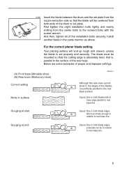
... surface EN0004-1 Although this side view cannot (B) show it, the edges of the blades run perfectly parallel to rear base line. For the correct planer blade setting Your planing surface will be centered from both blade edges (A) (B) protrudes too far in relation to rear base line. Gouging at end Cause:... parallel to the surface of the drum or set plate. Gouging at start Cause: One or both blades fails to have edge parallel to the rear base surface. 003880 Insert the blade between the drum and the set plate from the nozzle extraction side so that is set properly and ...
... surface EN0004-1 Although this side view cannot (B) show it, the edges of the blades run perfectly parallel to rear base line. For the correct planer blade setting Your planing surface will be centered from both blade edges (A) (B) protrudes too far in relation to rear base line. Gouging at end Cause:... parallel to the surface of the drum or set plate. Gouging at start Cause: One or both blades fails to have edge parallel to the rear base surface. 003880 Insert the blade between the drum and the set plate from the nozzle extraction side so that is set properly and ...
Owners Manual
Page 10
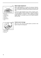
Set plate screw 4. Planer blade 6. Drum 1. After adjusting the blade height, tighten the set plate screws. Socket wrench 2. Installation bolt 3. Adjusting screw 7. Loosen the eight installation bolts and the set plate screws and the eight ..., store the socket wrench as shown in the figure to protrude it from the rear base, proceed as follows. Set plate 5. 1 3 1. Rear base 003879 2 4 5 6 7 Blade height adjustment Blade height adjustment is below the level of the rear base or protrudes too far from being lost. 1 2 3 10 However, if you notice that the...
Set plate screw 4. Planer blade 6. Drum 1. After adjusting the blade height, tighten the set plate screws. Socket wrench 2. Installation bolt 3. Adjusting screw 7. Loosen the eight installation bolts and the set plate screws and the eight ..., store the socket wrench as shown in the figure to protrude it from the rear base, proceed as follows. Set plate 5. 1 3 1. Rear base 003879 2 4 5 6 7 Blade height adjustment Blade height adjustment is below the level of the rear base or protrudes too far from being lost. 1 2 3 10 However, if you notice that the...

Owners Manual
Page 11
...2. Then move the tool gently forward. Apply pressure on the front of tool at a speed that the tool blades do not contact a workpiece and then sliding tool on and wait until the blades attain full speed. Front roller 11 Joint 2. Switch on the front roller. 1. 1 1. At the end of... jamming by raising the back end of planing 003886 Planing operation First, rest the tool front base flat upon the workpiece surface without the blades making any contact. Chip guide 2 003884 Nozzle assembly and joint (optional accessory) Nozzle assembly and joint are used when connecting the tool ...
...2. Then move the tool gently forward. Apply pressure on the front of tool at a speed that the tool blades do not contact a workpiece and then sliding tool on and wait until the blades attain full speed. Front roller 11 Joint 2. Switch on the front roller. 1. 1 1. At the end of... jamming by raising the back end of planing 003886 Planing operation First, rest the tool front base flat upon the workpiece surface without the blades making any contact. Chip guide 2 003884 Nozzle assembly and joint (optional accessory) Nozzle assembly and joint are used when connecting the tool ...
Owners Manual
Page 12
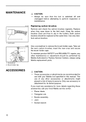
... use of any other accessories or attachments might present a risk of injury to remove the brush holder caps. Only use with your local Makita service center. • Planer blade • Triangular rule • Nozzle assembly • Joint • Socket wrench 12 If you need any assistance for its stated purpose. Brush holder...
... use of any other accessories or attachments might present a risk of injury to remove the brush holder caps. Only use with your local Makita service center. • Planer blade • Triangular rule • Nozzle assembly • Joint • Socket wrench 12 If you need any assistance for its stated purpose. Brush holder...

Parts Breakdown
Page 3
... F. WASHER 8, 4301BV KNOB, KP312 HEX BOLT, KP312 KNOB COVER, KP312 TIP GUIDE, KP312 P.H. BEARING 10, 2030 P.H. BOLT M6X12, 2030S MAKITA LABEL, HR5001C STEEL BALL 4.0, 5007NK COMPRESSION SPRING 3, KP312 HEX.SCREW M5X8, 4200N GUIDE RULE SHAFT, KP312 GUIDE PLATE R, KP312 STOP RING E-12, UM401DW DRUM, KP312 KEY 4, 2030S SCREW 5X13, 2030S HSS PLANER BLADE 312MM,KP312 SET PLATE 310, KP312 P.H. SCREW M5X16, 9505BH...
... F. WASHER 8, 4301BV KNOB, KP312 HEX BOLT, KP312 KNOB COVER, KP312 TIP GUIDE, KP312 P.H. BEARING 10, 2030 P.H. BOLT M6X12, 2030S MAKITA LABEL, HR5001C STEEL BALL 4.0, 5007NK COMPRESSION SPRING 3, KP312 HEX.SCREW M5X8, 4200N GUIDE RULE SHAFT, KP312 GUIDE PLATE R, KP312 STOP RING E-12, UM401DW DRUM, KP312 KEY 4, 2030S SCREW 5X13, 2030S HSS PLANER BLADE 312MM,KP312 SET PLATE 310, KP312 P.H. SCREW M5X16, 9505BH...

Flyer (English)
Page 1
Lock-on button for high rate of the base protects planer base and blades from becoming damaged ERGONOMIC MODEL KP312 For more info, call 1-800-4MAKITA makitatools.com Ideal cord location and length (33 ft.) helps prevent obstruction during long and repeated passes LEVELING THE ..., Log Home Manufacturers, Boat Fabricators and Many Other Trades FULL POWER Non-slip, long life poly "V" belt is designed to efficiently transfer power to the blades for consistent results EFFICIENCY Large ejection chute for continuous operation EXTENDED LIFE Foot located at rear of chip discharge;
Lock-on button for high rate of the base protects planer base and blades from becoming damaged ERGONOMIC MODEL KP312 For more info, call 1-800-4MAKITA makitatools.com Ideal cord location and length (33 ft.) helps prevent obstruction during long and repeated passes LEVELING THE ..., Log Home Manufacturers, Boat Fabricators and Many Other Trades FULL POWER Non-slip, long life poly "V" belt is designed to efficiently transfer power to the blades for consistent results EFFICIENCY Large ejection chute for continuous operation EXTENDED LIFE Foot located at rear of chip discharge;

Flyer (English)
Page 2
...provides high rate of accessories for 12-1/4" Planers. For a complete listing, please refer to the Makita General Catalog, or visit our website at rear of base protects planer base and blades from becoming damaged ■ Guide rule for accurate and maximum use of planing width ■ ... 1/8" 12,000 RPM 15.0 33 ft. 21-3/4" 39.7 lbs. 50.6 lbs. 088381-05088-3 Accessories Double Edged High Speed Steel Blades (B-02870) 12-1/4'' PLANER Model KP312 Makita offers a wide variety of chip discharge and helps prevent clogging from wet or dry wood chips ■ Ideal cord location and length ...
...provides high rate of accessories for 12-1/4" Planers. For a complete listing, please refer to the Makita General Catalog, or visit our website at rear of base protects planer base and blades from becoming damaged ■ Guide rule for accurate and maximum use of planing width ■ ... 1/8" 12,000 RPM 15.0 33 ft. 21-3/4" 39.7 lbs. 50.6 lbs. 088381-05088-3 Accessories Double Edged High Speed Steel Blades (B-02870) 12-1/4'' PLANER Model KP312 Makita offers a wide variety of chip discharge and helps prevent clogging from wet or dry wood chips ■ Ideal cord location and length ...


