
Owners Manual
Page 7
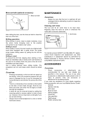
...The exceptions are obtained with wood drills equipped with a guide screw. Vent holes 1 002697 To maintain product SAFETY and RELIABILITY, repairs, carbon brush inspection and replacement, any other accessories or attachments might present a risk of symbol to use the blow-out bulb to break through . The...stuck bit can be kept clean. Drilling in metal To prevent the bit from slipping when starting a hole, make an indentation with your Makita tool specified in wood, metal or plastic materials, move the action mode changing lever to the position of injury to back out. Regularly ...
...The exceptions are obtained with wood drills equipped with a guide screw. Vent holes 1 002697 To maintain product SAFETY and RELIABILITY, repairs, carbon brush inspection and replacement, any other accessories or attachments might present a risk of symbol to use the blow-out bulb to break through . The...stuck bit can be kept clean. Drilling in metal To prevent the bit from slipping when starting a hole, make an indentation with your Makita tool specified in wood, metal or plastic materials, move the action mode changing lever to the position of injury to back out. Regularly ...
Parts Breakdown
Page 2
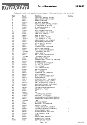
... BAFFLE PLATE, HP2050F TAPPING SCREW 4X65, HP2030 FIELD 115V, HP2050F N/A N/A MAKITA LABEL, DA3010F BRUSH HOLDER,HP2050F CARBON BRUSH SET CB-407, BO5030K CARBON BRUSH SET CB-407, FS4200 N/A SPACER, HP2050F BRUSH HOLDER, HP2050F SWITCH, HP2050F HANDLE COVER CPL., HP2050F TAPPING SCREW M4X25, HM1800... STRAIN RELIEF, 4323K TAPPING SCREW 4X18, 4323K CORD GUARD 8, 6824 CORD HEX. Parts Breakdown HP2050...
... BAFFLE PLATE, HP2050F TAPPING SCREW 4X65, HP2030 FIELD 115V, HP2050F N/A N/A MAKITA LABEL, DA3010F BRUSH HOLDER,HP2050F CARBON BRUSH SET CB-407, BO5030K CARBON BRUSH SET CB-407, FS4200 N/A SPACER, HP2050F BRUSH HOLDER, HP2050F SWITCH, HP2050F HANDLE COVER CPL., HP2050F TAPPING SCREW M4X25, HM1800... STRAIN RELIEF, 4323K TAPPING SCREW 4X18, 4323K CORD GUARD 8, 6824 CORD HEX. Parts Breakdown HP2050...

Technical Reference
Page 10
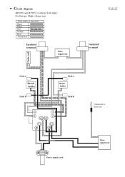
Circuit diagram HP2050F and HP2051F (equipped with flash light) For Europe, High voltage area Color index of lead wires Black White Red Orange Blue Transparent Insulated terminal Noise suppressor P 10 / 17 Insulated terminal Choke coil Field A Brush holder Field B Field A Brush holder Field B 2 3 4 1 M1 M2 C1 1 C2 2 LED circuit Connected to field core Noise suppressor Power supply cord LED
Circuit diagram HP2050F and HP2051F (equipped with flash light) For Europe, High voltage area Color index of lead wires Black White Red Orange Blue Transparent Insulated terminal Noise suppressor P 10 / 17 Insulated terminal Choke coil Field A Brush holder Field B Field A Brush holder Field B 2 3 4 1 M1 M2 C1 1 C2 2 LED circuit Connected to field core Noise suppressor Power supply cord LED
Technical Reference
Page 11
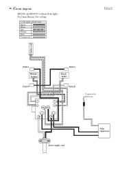
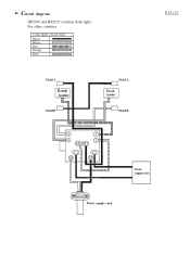
Circuit diagram HP2050 and HP2051 (without flash light) For Europe, High voltage area Color index of lead wires Black White Red Orange Blue Transparent Insulated terminal Noise suppressor P 11 / 17 Insulated terminal Choke coil Field A Brush holder Field B Field A Brush holder Field B 2 3 4 1 M1 M2 C1 1 C2 2 Power supply cord Connected to field core Noise suppressor
Circuit diagram HP2050 and HP2051 (without flash light) For Europe, High voltage area Color index of lead wires Black White Red Orange Blue Transparent Insulated terminal Noise suppressor P 11 / 17 Insulated terminal Choke coil Field A Brush holder Field B Field A Brush holder Field B 2 3 4 1 M1 M2 C1 1 C2 2 Power supply cord Connected to field core Noise suppressor
Technical Reference
Page 12
Circuit diagram HP2050 and HP2051 (without flash light) For Great Britain, low voltage Color index of lead wires Black White Red Orange Blue Transparent P 12 / 17 Choke coil Field A Brush holder Field B Field A Brush holder Field B 2 3 4 1 M1 M2 C1 1 C2 2 Connected to field core Noise suppressor Power supply cord
Circuit diagram HP2050 and HP2051 (without flash light) For Great Britain, low voltage Color index of lead wires Black White Red Orange Blue Transparent P 12 / 17 Choke coil Field A Brush holder Field B Field A Brush holder Field B 2 3 4 1 M1 M2 C1 1 C2 2 Connected to field core Noise suppressor Power supply cord
Technical Reference
Page 13
Circuit diagram HP2050 and HP2051 (without flash light) For other countries Color index of lead wires Black White Red Orange Blue P 13 / 17 Field A Brush holder Field B Field A Brush holder Field B 2 3 4 1 M1 M2 C1 1 C2 2 Noise suppressor Power supply cord
Circuit diagram HP2050 and HP2051 (without flash light) For other countries Color index of lead wires Black White Red Orange Blue P 13 / 17 Field A Brush holder Field B Field A Brush holder Field B 2 3 4 1 M1 M2 C1 1 C2 2 Noise suppressor Power supply cord

Technical Reference
Page 14
... connecting to field core * Field lead wire (white) for connecting to insulated terminal Brush holder Brush holder Fix the following lead wires with this lead holder. * Switch lead wire (blue) for connecting to brush holder * Field lead wire (white) for connecting to field core Noise suppressor Fig.... Fix the following lead wires with this lead holder. * Switch lead wire (red) for connecting to brush holder * Lead wire (black) connecting field terminals A and B Fix the lead wires passed through this portion * Lead wires of power supply ...
... connecting to field core * Field lead wire (white) for connecting to insulated terminal Brush holder Brush holder Fix the following lead wires with this lead holder. * Switch lead wire (blue) for connecting to brush holder * Field lead wire (white) for connecting to field core Noise suppressor Fig.... Fix the following lead wires with this lead holder. * Switch lead wire (red) for connecting to brush holder * Lead wire (black) connecting field terminals A and B Fix the lead wires passed through this portion * Lead wires of power supply ...
Technical Reference
Page 15
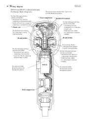
...terminal Fix with lead holder the lead wires passed through this portion Switch Fix Lead wire (black) connecting field terminals A and B, with * have to brush holder * Lead wire (black) connecting field terminals A and B Fix with lead holder the lead wires passed through this lead holder. * Switch lead... wire (red) for connecting to be set in the illustrated position. Wiring diagram P 15 / 17 HP2050 and HP2051 (without flash light) For Europe, High voltage area The electrical parts marked with lead holder. Fix the following lead wires with ...
...terminal Fix with lead holder the lead wires passed through this portion Switch Fix Lead wire (black) connecting field terminals A and B, with * have to brush holder * Lead wire (black) connecting field terminals A and B Fix with lead holder the lead wires passed through this lead holder. * Switch lead... wire (red) for connecting to be set in the illustrated position. Wiring diagram P 15 / 17 HP2050 and HP2051 (without flash light) For Europe, High voltage area The electrical parts marked with lead holder. Fix the following lead wires with ...
Technical Reference
Page 16
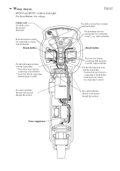
... Fix the following lead wires with this lead holder. * Switch lead wire (red) for connecting to brush holder * Lead wire (black) connecting field terminals A and B Fix with lead holder. Brush holder Fix the following lead wires with this lead holder. * Switch lead wire (blue) for connecting to... brush holder * Field lead wire (white) for connecting to switch Fix with lead holder the lead wires passed through this portion Noise suppressor Wiring diagram HP2050 and HP2051 (without flash light) For Great Britain, low voltage ...
... Fix the following lead wires with this lead holder. * Switch lead wire (red) for connecting to brush holder * Lead wire (black) connecting field terminals A and B Fix with lead holder. Brush holder Fix the following lead wires with this lead holder. * Switch lead wire (blue) for connecting to... brush holder * Field lead wire (white) for connecting to switch Fix with lead holder the lead wires passed through this portion Noise suppressor Wiring diagram HP2050 and HP2051 (without flash light) For Great Britain, low voltage ...
Technical Reference
Page 17
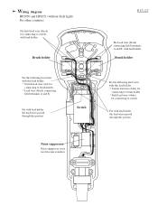
... Fix the following lead wires with this lead holder. * Switch lead wire (red) for connecting to brush holder * Lead wire (black) connecting field terminals A and B Fix with lead holder the lead wires passed through this portion Switch P 17 / 17 Fix Lead wire (...black) connecting field terminals A and B, with lead holder. Wiring diagram HP2050 and HP2051 (without flash light) For other countries Fix field lead wire (black) for connecting to switch Fix with lead holder the lead wires passed...
... Fix the following lead wires with this lead holder. * Switch lead wire (red) for connecting to brush holder * Lead wire (black) connecting field terminals A and B Fix with lead holder the lead wires passed through this portion Switch P 17 / 17 Fix Lead wire (...black) connecting field terminals A and B, with lead holder. Wiring diagram HP2050 and HP2051 (without flash light) For other countries Fix field lead wire (black) for connecting to switch Fix with lead holder the lead wires passed...
