
Owners Manual
Page 3
... moving parts. 4. This will do not allow persons unfamiliar with these instructions to prevent injury. 5. Do not leave the tool running. Do not touch the blade or the workpiece immediately after operation; Some material contains chemicals which it away from one is below when using only identical replacement parts. Power tool...
... moving parts. 4. This will do not allow persons unfamiliar with these instructions to prevent injury. 5. Do not leave the tool running. Do not touch the blade or the workpiece immediately after operation; Some material contains chemicals which it away from one is below when using only identical replacement parts. Power tool...
Owners Manual
Page 5
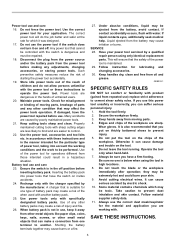
...the trigger lock-button from the cutting head surface. Sleeve 3. Screws Install the sleeve and tighten the three screws after inserting the center blade, side blade L & R into the tool, always check to see that the switch trigger actuates properly and returns to the "OFF" position when ...cause injury. Hex wrench 2 3 009017 Remove the three screws which secure the cutting head. Otherwise it can cause serious injury. 1 1. Side blade L 3. After use, always press in the OFF position. Removing cutting head Use the hex wrench to remove it left and right alternately. ...
...the trigger lock-button from the cutting head surface. Sleeve 3. Screws Install the sleeve and tighten the three screws after inserting the center blade, side blade L & R into the tool, always check to see that the switch trigger actuates properly and returns to the "OFF" position when ...cause injury. Hex wrench 2 3 009017 Remove the three screws which secure the cutting head. Otherwise it can cause serious injury. 1 1. Side blade L 3. After use, always press in the OFF position. Removing cutting head Use the hex wrench to remove it left and right alternately. ...
Owners Manual
Page 6
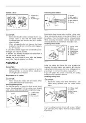
... by grabbing the two flat parts on the spindle still with the provided wrench while keeping the spindle still by placing another wrench. Center blade 4. Replacing cutting head for temporarily hooking the tool. Hex wrench 1 009021 009050 2. When not in use, store the hex wrench as...hook, widen it in the directions of gauge 16 (Optional Accessory) 1. The bearing assembly provided on either side of the arrow (2). 1. Side blade 2. It can be installed on the tool is convenient for capacity of arrow (1) and raise it by referring to the section titled " Installing cutting...
... by grabbing the two flat parts on the spindle still with the provided wrench while keeping the spindle still by placing another wrench. Center blade 4. Replacing cutting head for temporarily hooking the tool. Hex wrench 1 009021 009050 2. When not in use, store the hex wrench as...hook, widen it in the directions of gauge 16 (Optional Accessory) 1. The bearing assembly provided on either side of the arrow (2). 1. Side blade 2. It can be installed on the tool is convenient for capacity of arrow (1) and raise it by referring to the section titled " Installing cutting...

Owners Manual
Page 7
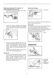
... 7 Then tighten the three screws with the workpiece surface. Lubrication 1 2 3 4 5 1. Center blade 4. Lubricate 009022 Before operation, lubricate the contact point of the center blade near the cutting head. To keep good cutting performance, use lubricant from time to slip in the holders...is switched off and unplugged before attempting to perform inspection or maintenance. Side blade R 5. Screws 2. First remove the holder by unscrewing the hex socket head bolt. 2 1. Side blade L 3. Hex socket head bolt 2 009049 Use a screwdriver to adjust it...
... 7 Then tighten the three screws with the workpiece surface. Lubrication 1 2 3 4 5 1. Center blade 4. Lubricate 009022 Before operation, lubricate the contact point of the center blade near the cutting head. To keep good cutting performance, use lubricant from time to slip in the holders...is switched off and unplugged before attempting to perform inspection or maintenance. Side blade R 5. Screws 2. First remove the holder by unscrewing the hex socket head bolt. 2 1. Side blade L 3. Hex socket head bolt 2 009049 Use a screwdriver to adjust it...
Owners Manual
Page 8
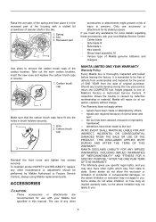
...state. Should any assistance for use accessory or attachment for the period of injury to be performed by defective workmanship or material, Makita will repair (or at our option, replace) without charge. To maintain product SAFETY and RELIABILITY, repairs, any other rights ...others: repairs are recommended for more details regarding these accessories, ask your Makita tool specified in the recessed part of the housing with your local Makita Service Center. • Center blade • Side blade R • Side blade L • Hex wrench • Shear head assembly 16 •...
...state. Should any assistance for use accessory or attachment for the period of injury to be performed by defective workmanship or material, Makita will repair (or at our option, replace) without charge. To maintain product SAFETY and RELIABILITY, repairs, any other rights ...others: repairs are recommended for more details regarding these accessories, ask your Makita tool specified in the recessed part of the housing with your local Makita Service Center. • Center blade • Side blade R • Side blade L • Hex wrench • Shear head assembly 16 •...
Parts Breakdown
Page 2
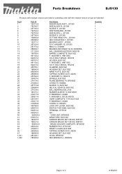
... P. BOLT M5X20, HR2010 CLAMPER, BJS130Z HOUSING SET, BJS130Z NAME PLATE, BJS130Z TAPPING SCREW 4X18, 4323K F. WASHER 5, HM1100C H.S.H. Parts Breakdown BJS130 Products with multiple versions are listed in subsiding order with the newest version on top not indented Fig # 1 2 3 4 5 6 7...194427-5 195021-6 638433-5 263032-0 419307-7 265995-6 188540-9 281220-7 783202-0 Part Name SHEAR HEAD ASS'Y, JS1300 SIDE BLADE R, JS1300 SLEEVE 5, JS1300 CENTER BLADE, JS1300 SIDE BLADE L, JS1300 SLEEVE 5, JS1300 CUTTING HEAD CPL., JS1300 HEX.S.HEAD BOLT, JS1300 BEARING ASS'Y, JS1300 FLAT WASHER 10,...
... P. BOLT M5X20, HR2010 CLAMPER, BJS130Z HOUSING SET, BJS130Z NAME PLATE, BJS130Z TAPPING SCREW 4X18, 4323K F. WASHER 5, HM1100C H.S.H. Parts Breakdown BJS130 Products with multiple versions are listed in subsiding order with the newest version on top not indented Fig # 1 2 3 4 5 6 7...194427-5 195021-6 638433-5 263032-0 419307-7 265995-6 188540-9 281220-7 783202-0 Part Name SHEAR HEAD ASS'Y, JS1300 SIDE BLADE R, JS1300 SLEEVE 5, JS1300 CENTER BLADE, JS1300 SIDE BLADE L, JS1300 SLEEVE 5, JS1300 CUTTING HEAD CPL., JS1300 HEX.S.HEAD BOLT, JS1300 BEARING ASS'Y, JS1300 FLAT WASHER 10,...


