
Owners Manual
Page 2
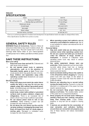
...notice. • Note: Specifications may differ from country to your finger on . Remove any adjusting key or wrench before plugging in moving parts. 15. Dress properly. GEA002-3 GENERAL SAFETY RULES WARNING! Distractions can cause you are doing and use a power tool while you to ...Steel up to a rotating part of the power tool may result in the presence of dust extraction and collection facilities, ensure these devices can be caught in . Water entering a power tool will reduce personal injuries. 11. A wrench or a key left attached to 600 N/mm2 BJS130 1.3 mm (18 ga...
...notice. • Note: Specifications may differ from country to your finger on . Remove any adjusting key or wrench before plugging in moving parts. 15. Dress properly. GEA002-3 GENERAL SAFETY RULES WARNING! Distractions can cause you are doing and use a power tool while you to ...Steel up to a rotating part of the power tool may result in the presence of dust extraction and collection facilities, ensure these devices can be caught in . Water entering a power tool will reduce personal injuries. 11. A wrench or a key left attached to 600 N/mm2 BJS130 1.3 mm (18 ga...
Owners Manual
Page 3
... person using the tool in a hazardous situation. Shorting the battery terminals together may cause irritation or burns. Liquid ejected from moving parts, breakage of parts and any other condition that is maintained. 29. This will do not allow persons unfamiliar with the switch is not in the...that have the switch on invites accidents. 24. SERVICE 28. Secure the workpiece firmly. 3. It is below when using only identical replacement parts. Operate the tool only when hand-held. 7. Take caution to cement shear safety rules. Any power tool that can cause serious accident ...
... person using the tool in a hazardous situation. Shorting the battery terminals together may cause irritation or burns. Liquid ejected from moving parts, breakage of parts and any other condition that is maintained. 29. This will do not allow persons unfamiliar with the switch is not in the...that have the switch on invites accidents. 24. SERVICE 28. Secure the workpiece firmly. 3. It is below when using only identical replacement parts. Operate the tool only when hand-held. 7. Take caution to cement shear safety rules. Any power tool that can cause serious accident ...
Owners Manual
Page 4
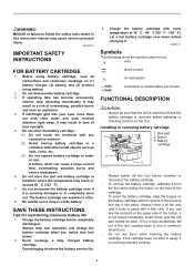
... cartridge in locations where the temperature may result in loss of the tool, causing injury to you or someone around you can see the red part on the upper side of the cartridge. • To insert the battery cartridge, align the tongue on (1) battery charger, (2) battery, and (3) product... of the battery cartridge. • To remove the battery cartridge, withdraw it from the tool while sliding the button on the tool. Red part 1 2. SAVE THESE INSTRUCTIONS. Never recharge a fully charged battery cartridge. If the cartridge does not slide in the housing and slip it is...
... cartridge in locations where the temperature may result in loss of the tool, causing injury to you or someone around you can see the red part on the upper side of the cartridge. • To insert the battery cartridge, align the tongue on (1) battery charger, (2) battery, and (3) product... of the battery cartridge. • To remove the battery cartridge, withdraw it from the tool while sliding the button on the tool. Red part 1 2. SAVE THESE INSTRUCTIONS. Never recharge a fully charged battery cartridge. If the cartridge does not slide in the housing and slip it is...
Owners Manual
Page 6
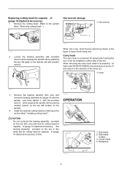
... gauge 16 (Optional Accessory). It can be installed on the spindle still with provided wrench while keeping the spindle still by grabbing the two flat parts on either side of arrow (1) and raise it in the figure to keep it with the provided wrench while keeping the spindle still by placing...
... gauge 16 (Optional Accessory). It can be installed on the spindle still with provided wrench while keeping the spindle still by grabbing the two flat parts on either side of arrow (1) and raise it in the figure to keep it with the provided wrench while keeping the spindle still by placing...
Owners Manual
Page 8
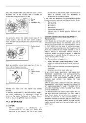
.... Should any other accessories or attachments might present a risk of injury to persons. EN0006-1 8 Recessed part 006816 2 3 Use pliers to remove the carbon brush caps of Makita's Factory or Authorized Service Centers. Hole 2. To maintain product SAFETY and RELIABILITY, repairs, any assistance for...the trouble is caused by defective workmanship or material, Makita will repair (or at our option, replace) without charge. Raise the arm part of the spring and then place it in the recessed part of the housing with your local Makita Service Center. • Center blade • ...
.... Should any other accessories or attachments might present a risk of injury to persons. EN0006-1 8 Recessed part 006816 2 3 Use pliers to remove the carbon brush caps of Makita's Factory or Authorized Service Centers. Hole 2. To maintain product SAFETY and RELIABILITY, repairs, any assistance for...the trouble is caused by defective workmanship or material, Makita will repair (or at our option, replace) without charge. Raise the arm part of the spring and then place it in the recessed part of the housing with your local Makita Service Center. • Center blade • ...
Parts Breakdown
Page 2
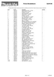
...1 1 1 1 1 1 1 1 1 1 1 1 9 1 1 1 1 1 1 1 1 1 1 1 1 1 1 1 1 1 1 1 1 1 1 2 1 2 1 1 1 Page 2 of 2 8/18/2010 BOLT M5X20, HR2010 HOLDER, BJS130Z F. WASHER 5, HM1100C H.S.H. Parts Breakdown BJS130 Products with multiple versions are listed in subsiding order with the newest version on top not indented Fig # 1 2 3 4 5 6 7 8 9 10 11 12 13 14 15 16...650575-5 643812-4 643843-3 638426-2 619237-4 194427-5 195021-6 638433-5 263032-0 419307-7 265995-6 188540-9 281220-7 783202-0 Part Name SHEAR HEAD ASS'Y, JS1300 SIDE BLADE R, JS1300 SLEEVE 5, JS1300 CENTER BLADE, JS1300 SIDE BLADE L, JS1300 SLEEVE ...
...1 1 1 1 1 1 1 1 1 1 1 1 9 1 1 1 1 1 1 1 1 1 1 1 1 1 1 1 1 1 1 1 1 1 1 2 1 2 1 1 1 Page 2 of 2 8/18/2010 BOLT M5X20, HR2010 HOLDER, BJS130Z F. WASHER 5, HM1100C H.S.H. Parts Breakdown BJS130 Products with multiple versions are listed in subsiding order with the newest version on top not indented Fig # 1 2 3 4 5 6 7 8 9 10 11 12 13 14 15 16...650575-5 643812-4 643843-3 638426-2 619237-4 194427-5 195021-6 638433-5 263032-0 419307-7 265995-6 188540-9 281220-7 783202-0 Part Name SHEAR HEAD ASS'Y, JS1300 SIDE BLADE R, JS1300 SLEEVE 5, JS1300 CENTER BLADE, JS1300 SIDE BLADE L, JS1300 SLEEVE ...


