
Owners Manual
Page 1
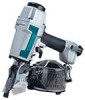
...Net weight I 2.2 kg (4.9 Ibs) I h i n c n c T A h i n L A - - - hose diameter Dimensions (L x W x H) 6.5 mm (1/4") 332 mm x 127 mm x 31 7 mm (13-1/16" x 5" x 12-1/2") * Manufacturer reserves the right to change specifications without notice. * Note: Specifications may differ from country to country. \ A / A R h l l h l C . A I I Min. En. , , n , , v n a r r n n m ~ --L+., ~ c ~ n - - Construction Coil Nailer MODEL AN61 1 INSTRUCTION MANUAL SPECIFICATIONS Air pressure I Applicable length I Nail capacity 4.5 - 8.5 kgf/cmZG ( 6 5 - 120 PSIG) 32 mm, 38 mm, 45 mm, 50 mm...
...Net weight I 2.2 kg (4.9 Ibs) I h i n c n c T A h i n L A - - - hose diameter Dimensions (L x W x H) 6.5 mm (1/4") 332 mm x 127 mm x 31 7 mm (13-1/16" x 5" x 12-1/2") * Manufacturer reserves the right to change specifications without notice. * Note: Specifications may differ from country to country. \ A / A R h l l h l C . A I I Min. En. , , n , , v n a r r n n m ~ --L+., ~ c ~ n - - Construction Coil Nailer MODEL AN61 1 INSTRUCTION MANUAL SPECIFICATIONS Air pressure I Applicable length I Nail capacity 4.5 - 8.5 kgf/cmZG ( 6 5 - 120 PSIG) 32 mm, 38 mm, 45 mm, 50 mm...

Owners Manual
Page 2
... light but not loose clothing. Sleeves should conform with the requirements of safety eye protection equipment by the tool operators and by other persons in the immediate working area. Wear hearing protection t o protect your eyes from dust or nail injury. For personal safety and proper operation and maintenance of alcohol, drugs or the like. Handle the tool carefully. IMPORTANT SAFETY INSTRUCTIONS WARNING: WHEN USING THIS TOOL...
... light but not loose clothing. Sleeves should conform with the requirements of safety eye protection equipment by the tool operators and by other persons in the immediate working area. Wear hearing protection t o protect your eyes from dust or nail injury. For personal safety and proper operation and maintenance of alcohol, drugs or the like. Handle the tool carefully. IMPORTANT SAFETY INSTRUCTIONS WARNING: WHEN USING THIS TOOL...

Owners Manual
Page 3
General Tool Handling Guidelines: 1. No horseplay. 6. Do not use the tool near volatile, flammable materials such as a working implement. 5. The area should be sufficiently illuminated to assure safe operations. free. Do not operate the tool with a finger on the trigger. 7. Sparks sometimes fly when the tool is placed firmly against the workpiece. 4. they will ignite and explode, causing serious injury. Be especially...
General Tool Handling Guidelines: 1. No horseplay. 6. Do not use the tool near volatile, flammable materials such as a working implement. 5. The area should be sufficiently illuminated to assure safe operations. free. Do not operate the tool with a finger on the trigger. 7. Sparks sometimes fly when the tool is placed firmly against the workpiece. 4. they will ignite and explode, causing serious injury. Be especially...

Owners Manual
Page 4
... specified air pressure of 8.5 kgf/cm'G (120 PSIG). L-Shutter Operate the tool within prescribed limits. In certain cases, shutters should be in the vicinity. Do not exceed the recommended max. operating pressure of 4.5 - 8.5 kgf/cm'G (65- 120 PSIG) for safety and longer tool life. Children especially must be kept on and not removed. *Only those involved in the work should be used...
... specified air pressure of 8.5 kgf/cm'G (120 PSIG). L-Shutter Operate the tool within prescribed limits. In certain cases, shutters should be in the vicinity. Do not exceed the recommended max. operating pressure of 4.5 - 8.5 kgf/cm'G (65- 120 PSIG) for safety and longer tool life. Children especially must be kept on and not removed. *Only those involved in the work should be used...

Owners Manual
Page 5
... (carbon dioxide, oxgen, nitrogen, hydrogen, air, etc.) or combustible gas (hydrogen, propane, acetylene, etc.) is pressed against the wood. Tighten as a power source for its overall condition and loose screws before operation. COMPRESSED AIR *Always check the tool for this tool, the tool will explode and cause serious injury. The tool must work only when both actions are in working order before operation. Test...
... (carbon dioxide, oxgen, nitrogen, hydrogen, air, etc.) or combustible gas (hydrogen, propane, acetylene, etc.) is pressed against the wood. Tighten as a power source for its overall condition and loose screws before operation. COMPRESSED AIR *Always check the tool for this tool, the tool will explode and cause serious injury. The tool must work only when both actions are in working order before operation. Test...
Owners Manual
Page 6
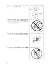
Trigger /,--.' . Change lever Trigger lock Check walls, ceilings, floors, roofing and the like carefully to the LOCK position. Use only nails specified in this manual. Make sure that the trigger is locked when the change lever is set to avoid possible electrical shock, gas leakage, explosions, etc. Do not permit those uninstructed t o use of any other nails may cause malfunction of the tool. The use the tool. ..... 6 caused by striking live wires, conduits or gas pipes.
Trigger /,--.' . Change lever Trigger lock Check walls, ceilings, floors, roofing and the like carefully to the LOCK position. Use only nails specified in this manual. Make sure that the trigger is locked when the change lever is set to avoid possible electrical shock, gas leakage, explosions, etc. Do not permit those uninstructed t o use of any other nails may cause malfunction of the tool. The use the tool. ..... 6 caused by striking live wires, conduits or gas pipes.

Owners Manual
Page 7
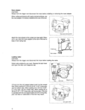
...air hose t o prevent danger if there is sudden jerking or catching. - Make sure there is no one below when working in the wood. A nail will be thrown and hit someone, or the tool itself can react dangerously. Make sure no one is nearby before nailing. Nails may be bent or the tool can perform nailing operations... with care. Never attempt to nail from the top t o the bottom. When nailing against perpendicular surface, nail from both the inside and outside at the same time. The nail may rip through...
...air hose t o prevent danger if there is sudden jerking or catching. - Make sure there is no one below when working in the wood. A nail will be thrown and hit someone, or the tool itself can react dangerously. Make sure no one is nearby before nailing. Nails may be bent or the tool can perform nailing operations... with care. Never attempt to nail from the top t o the bottom. When nailing against perpendicular surface, nail from both the inside and outside at the same time. The nail may rip through...
Owners Manual
Page 8
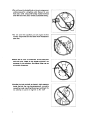
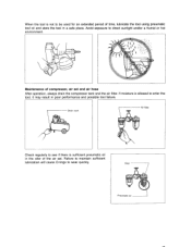
... the loaded tool or the air compressor under pressure for a long time out in the When the air hose is caused by rough handling (dropping or striking). Do not attempt t o carve or engrave on the trigger or hand it setting. *Do not point the ejection port at anyone in the sun. Handle the tool carefully as there is high pressure inside the tool that dust, sand, chips...
... the loaded tool or the air compressor under pressure for a long time out in the When the air hose is caused by rough handling (dropping or striking). Do not attempt t o carve or engrave on the trigger or hand it setting. *Do not point the ejection port at anyone in the sun. Handle the tool carefully as there is high pressure inside the tool that dust, sand, chips...

Owners Manual
Page 9
... wrong or out of the nails: 1. Change lever Perform cleaning and maintenance right after finishing the job. Stop nailing operations immediately if you notice .. When unattended. 2. Lubricate moving the tool t o a new location. Wipe off all of the ordinary with the tool. .Always disconnect the air hose and remove all dust from the parts. When not operating the tool, always lock the trigger by turning the change lever to prevent rusting and...
... wrong or out of the nails: 1. Change lever Perform cleaning and maintenance right after finishing the job. Stop nailing operations immediately if you notice .. When unattended. 2. Lubricate moving the tool t o a new location. Wipe off all of the ordinary with the tool. .Always disconnect the air hose and remove all dust from the parts. When not operating the tool, always lock the trigger by turning the change lever to prevent rusting and...

Owners Manual
Page 10
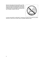
SAVE THESE INSTRUCTIONS. 10 Do not modify tool without authorization from Makita. Ask Makita's Factory or Authorized service center for periodical inspection of the tool. To maintain product SAFETY and RELIABILITY, maintenance and repairs should be performed by Makita Authorized or Factory Service Centers, always using Makita replacement parts. .Do not operate this tool if it does not contain a legible WARNING LABEL.
SAVE THESE INSTRUCTIONS. 10 Do not modify tool without authorization from Makita. Ask Makita's Factory or Authorized service center for periodical inspection of the tool. To maintain product SAFETY and RELIABILITY, maintenance and repairs should be performed by Makita Authorized or Factory Service Centers, always using Makita replacement parts. .Do not operate this tool if it does not contain a legible WARNING LABEL.
Owners Manual
Page 11
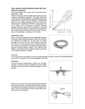
... when the interval between nailing frequency, applicable pressure and compressor air output. I * When an air set (oiler, regulator, air filter) as close as possible to assure cost-efficient operation. Pressure regulators must be done before and after pneu- Adjust the oiler so that has ample pressure and air output to assure continuous, efficient nailing operation. I matic tool oil is higher. TOOL INSTALLATION INSTRUCTIONS AND USE Selecting compressor The air compressor must comply with...
... when the interval between nailing frequency, applicable pressure and compressor air output. I * When an air set (oiler, regulator, air filter) as close as possible to assure cost-efficient operation. Pressure regulators must be done before and after pneu- Adjust the oiler so that has ample pressure and air output to assure continuous, efficient nailing operation. I matic tool oil is higher. TOOL INSTALLATION INSTRUCTIONS AND USE Selecting compressor The air compressor must comply with...
Owners Manual
Page 12
... adapter Loading nailer I 12 Coil support plate When nailing workpieces with the coil support plate set it from being lost. Depress the latch lever and open the door and magazine cap. I CAUTION: Always lock the trigger and disconnect the hose before installing or removing the nose adapter. It is operated with easily-marred surfaces, use the top step. Select nails suitable for your work. When loading 45 or 50 mm (1-3/4", 2") long nails, use...
... adapter Loading nailer I 12 Coil support plate When nailing workpieces with the coil support plate set it from being lost. Depress the latch lever and open the door and magazine cap. I CAUTION: Always lock the trigger and disconnect the hose before installing or removing the nose adapter. It is operated with easily-marred surfaces, use the top step. Select nails suitable for your work. When loading 45 or 50 mm (1-3/4", 2") long nails, use...
Owners Manual
Page 13
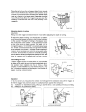
... depth of nailing is set to reach the feed claw. Adjuster Connecting air hose Lock the trigger. It will point to drive a nail carefully and very accurately. The depth can be in the slot in the magazine. A hose coupling must be changed in the feed claw. The depth of nailing. Generally speaking, the tool service life will discharge at the time the air supply coupling is used with ./ lower air pressure...
... depth of nailing is set to reach the feed claw. Adjuster Connecting air hose Lock the trigger. It will point to drive a nail carefully and very accurately. The depth can be in the slot in the magazine. A hose coupling must be changed in the feed claw. The depth of nailing. Generally speaking, the tool service life will discharge at the time the air supply coupling is used with ./ lower air pressure...
Owners Manual
Page 14
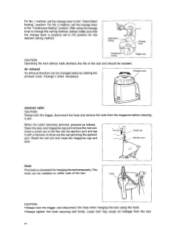
... nailer CAUTION: Always lock the trigger, disconnect the hose and remove the nails from the tool. 14 This hook can be installed on either side of the tool. After using the hook. *Always tighten the hook securing bolt firmly. Change it with a hammer to the position for hanging the tool temporarily. Hook \ CAUTION: *Always lock the trigger and disconnect the hose when hanging the tool using the change lever to change the nailing...
... nailer CAUTION: Always lock the trigger, disconnect the hose and remove the nails from the tool. 14 This hook can be installed on either side of the tool. After using the hook. *Always tighten the hook securing bolt firmly. Change it with a hammer to the position for hanging the tool temporarily. Hook \ CAUTION: *Always lock the trigger and disconnect the hose when hanging the tool using the change lever to change the nailing...
Owners Manual
Page 16
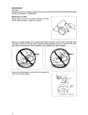
I I 1 Make sure that the trigger is locked and the air hose is set to perform inspection or maintenance. MAINTENANCE CAUTION: Always be sure that the trigger is locked when the change lever is disconnected from the tool before attempting to the LOCK position. ' Change Trigger lock 16 Tighten as required. Make sure all safety systems are performed. It must not operate if only the trigger is pulled or if only the...
I I 1 Make sure that the trigger is locked and the air hose is set to perform inspection or maintenance. MAINTENANCE CAUTION: Always be sure that the trigger is locked when the change lever is disconnected from the tool before attempting to the LOCK position. ' Change Trigger lock 16 Tighten as required. Make sure all safety systems are performed. It must not operate if only the trigger is pulled or if only the...
Owners Manual
Page 17
... of compressor, air set . I Drain cock 7 Air Check regularly to see if there is allowed to enter the tool, it may result in poor performance and possible tool failure. Avoid exposure to wear quickly. Maintenance of time, lubricate the tool using pneumatic tool oil and store the tool in the oiler of the air set and air hose After operation, always drain the compressor tank and the air filter...
... of compressor, air set . I Drain cock 7 Air Check regularly to see if there is allowed to enter the tool, it may result in poor performance and possible tool failure. Avoid exposure to wear quickly. Maintenance of time, lubricate the tool using pneumatic tool oil and store the tool in the oiler of the air set and air hose After operation, always drain the compressor tank and the air filter...
Owners Manual
Page 18
To maintain product SAFETY and RELIABILITY, maintenance and repairs should be directed away from sharp edges and areas which it may lead to damage or abrasion to the hose. Also, route the hose away from chemicals (thinner, strong acids or alkalis). Hoses must also be performed by Makita Authorized or Factory Service Centers, always using Makita replacement parts. 18 Keep the air hose away from heat (over 6OoC,over 140°F), away from obstacles which may become dangerously caught on during operation.
To maintain product SAFETY and RELIABILITY, maintenance and repairs should be directed away from sharp edges and areas which it may lead to damage or abrasion to the hose. Also, route the hose away from chemicals (thinner, strong acids or alkalis). Hoses must also be performed by Makita Authorized or Factory Service Centers, always using Makita replacement parts. 18 Keep the air hose away from heat (over 6OoC,over 140°F), away from obstacles which may become dangerously caught on during operation.

Owners Manual
Page 19
... the date of Makita's Factory or Authorized Service Centers. MAKITA LIMITEDONE YEAR WARRANTY Warranty Policy Every Makita tool is caused by others: a repairs are required because of normal wear and tear: a The tool has been abused, misused or improperly maintained ; 0 alterations have been made or attempted by defective workmanship or material, Makita will repair (or at our option, replace) without charge. It...
... the date of Makita's Factory or Authorized Service Centers. MAKITA LIMITEDONE YEAR WARRANTY Warranty Policy Every Makita tool is caused by others: a repairs are required because of normal wear and tear: a The tool has been abused, misused or improperly maintained ; 0 alterations have been made or attempted by defective workmanship or material, Makita will repair (or at our option, replace) without charge. It...
Parts Breakdown
Page 2
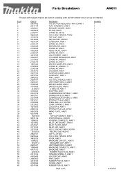
... COMPLETE, AN611 MAGAZINE, AN611 RUBBER PLATE 6-20, AN451 TENSION SPRING 5, AN611 HOLDER CAP, AN451 PIN 4, AN611 RUBBER PIN 9.5, AN611 COVER, AN611 RUBBER PIN 9.5, AN611 Page 2 of 4 Quantity 1 1 1 1 1 4 1 1 1 1 1 1 1 1 1 1 1 1 1 1 1 1 1 1 1 4 1 1 1 1 1 1 1 8 1 1 1 1 2 1 1 1 1 1 1 1 1 1 1 1 3 1 1 1 1 1 1 1 1 1 1 1 1 1 8/18/2010 BOLT M5X25, AF502 TOP CAP, AN611 HEX NUT M5, HR2410 CUSHION R, AN611 O RING 39, AN611 SEPARATOR, AN611 O RING 23, AN611 HEAD VALVE, AN611 O RING 48, AN611 VALVE SHEET, AN611 CYLINDER SEPARATOR, AN611 O RING 67, AN8300 O RING 36, AN611 DRIVER COMPLETE, AN611 O RING...
... COMPLETE, AN611 MAGAZINE, AN611 RUBBER PLATE 6-20, AN451 TENSION SPRING 5, AN611 HOLDER CAP, AN451 PIN 4, AN611 RUBBER PIN 9.5, AN611 COVER, AN611 RUBBER PIN 9.5, AN611 Page 2 of 4 Quantity 1 1 1 1 1 4 1 1 1 1 1 1 1 1 1 1 1 1 1 1 1 1 1 1 1 4 1 1 1 1 1 1 1 8 1 1 1 1 2 1 1 1 1 1 1 1 1 1 1 1 3 1 1 1 1 1 1 1 1 1 1 1 1 1 8/18/2010 BOLT M5X25, AF502 TOP CAP, AN611 HEX NUT M5, HR2410 CUSHION R, AN611 O RING 39, AN611 SEPARATOR, AN611 O RING 23, AN611 HEAD VALVE, AN611 O RING 48, AN611 VALVE SHEET, AN611 CYLINDER SEPARATOR, AN611 O RING 67, AN8300 O RING 36, AN611 DRIVER COMPLETE, AN611 O RING...
Parts Breakdown
Page 3
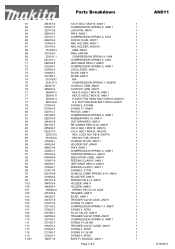
...16, AN611 1 CUP WASHER 5, AN611 1 RETAINING RING R-24, AN611 1 H.S.H. LOCK NUT M5-8, 5007FK 1 HEX NUT M5, HR2410 1 CHANGE PLATE, AN611 1 HOLDER CAP, AN451 1 PIN 4, AN611 1 COMPRESSION SPRING 3, AN611 1 TORSION SPRING 6, AN611 1 INDICATION LABEL, AN611 1 FEEDING CLAW R, AN611 1 URETHANE RING 3, AN451 1 FEEDING CLAW F, AN611 1 O RING 6, 5177B 1 CONICAL COMP SPRING 9-16, AN611 1 ADJUSTER, AN611 1 SPRING PIN 2-14, AN611 1 HOLDER, AN611 1 HOLDER, AN621 1 SPRING PIN 2.5-16, 420S 1 TRIGGER, AN611 1 IDLER, AN611 1 TRIGGER VALVE CASE, AN611 1 O RING...
...16, AN611 1 CUP WASHER 5, AN611 1 RETAINING RING R-24, AN611 1 H.S.H. LOCK NUT M5-8, 5007FK 1 HEX NUT M5, HR2410 1 CHANGE PLATE, AN611 1 HOLDER CAP, AN451 1 PIN 4, AN611 1 COMPRESSION SPRING 3, AN611 1 TORSION SPRING 6, AN611 1 INDICATION LABEL, AN611 1 FEEDING CLAW R, AN611 1 URETHANE RING 3, AN451 1 FEEDING CLAW F, AN611 1 O RING 6, 5177B 1 CONICAL COMP SPRING 9-16, AN611 1 ADJUSTER, AN611 1 SPRING PIN 2-14, AN611 1 HOLDER, AN611 1 HOLDER, AN621 1 SPRING PIN 2.5-16, 420S 1 TRIGGER, AN611 1 IDLER, AN611 1 TRIGGER VALVE CASE, AN611 1 O RING...


