
Owners Manual
Page 2
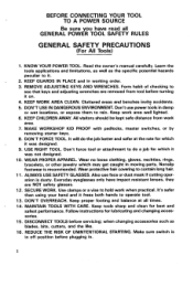
... DISCONNECT TOOLS before plugging in working order. 3.REMOVE ADJUSTING KEYS AND WRENCHES. KNOW YOUR POWER TOOL. KEEP GUARDS IN PLACE and in . Also use power tools in moving parts. Learn the tools applications and limitations, as well as blades, bits, cutters, and the like. 16. DON'T ... sure switch is in off position before servicing; MAKE WORKSHOP KID PROOF with padlocks, master switches, or by removing starter keys. 8. IO. Use clamps or a vise t o hold work area. 7. Keep tools sharp and clean for lubricating and changing accessories. 15. when changing accessories such...
... DISCONNECT TOOLS before plugging in working order. 3.REMOVE ADJUSTING KEYS AND WRENCHES. KNOW YOUR POWER TOOL. KEEP GUARDS IN PLACE and in . Also use power tools in moving parts. Learn the tools applications and limitations, as well as blades, bits, cutters, and the like. 16. DON'T ... sure switch is in off position before servicing; MAKE WORKSHOP KID PROOF with padlocks, master switches, or by removing starter keys. 8. IO. Use clamps or a vise t o hold work area. 7. Keep tools sharp and clean for lubricating and changing accessories. 15. when changing accessories such...
Owners Manual
Page 3
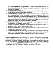
...be properly repaired or replaced. 20. as well as that it comes t o a complete stop. 22. CHECK DAMAGED PARTS. PROPER GROUNDING. 17. The use of improper accessories may affect its intended function - A guard or other part that is the same as damage t o the tool. NEVER STAND ON TOOL.... DIRECTION OF FEED. If in SERIOUS INJURY t o the user - Before further use t o protect the operator from electric shock. 23. Replace or repair damaged or worn cord immediately. A power source with voltage less than that ...
...be properly repaired or replaced. 20. as well as that it comes t o a complete stop. 22. CHECK DAMAGED PARTS. PROPER GROUNDING. 17. The use of improper accessories may affect its intended function - A guard or other part that is the same as damage t o the tool. NEVER STAND ON TOOL.... DIRECTION OF FEED. If in SERIOUS INJURY t o the user - Before further use t o protect the operator from electric shock. 23. Replace or repair damaged or worn cord immediately. A power source with voltage less than that ...
Owners Manual
Page 4
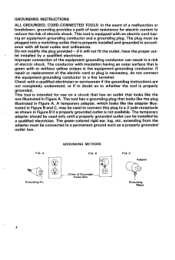
...is properly installed and grounded in Figure A. A temporary adapter, which looks like the plug illustrated in accord- extending from the adapter must be used t o connect this plug t o a 2-pole receptacle as a properly grounded outlet box. let installed by a qualified electrician. GROUNDING INSTRUCTIONS ...ALL GROUNDED, CORD-CONNECTED TOOLS: In the event of a malfunction or breakdown, grounding provides a path of least resistance for use on a circuit that has an outlet that looks like the one illustrated in a risk of electric shock. The conductor with insulation...
...is properly installed and grounded in Figure A. A temporary adapter, which looks like the plug illustrated in accord- extending from the adapter must be used t o connect this plug t o a 2-pole receptacle as a properly grounded outlet box. let installed by a qualified electrician. GROUNDING INSTRUCTIONS ...ALL GROUNDED, CORD-CONNECTED TOOLS: In the event of a malfunction or breakdown, grounding provides a path of least resistance for use on a circuit that has an outlet that looks like the one illustrated in a risk of electric shock. The conductor with insulation...
Owners Manual
Page 5
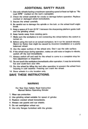
...Before Operating Grinder 1. Do not overtighten wheel nut. 6. Replace cracked wheel immediately. 4. Always use the side surface. 10. Always switch off the tool immediately. 11. Use grinding wheel suitable for cracks or damage before the switch is turned on the tool's nameplate... carefully. 4. Store wheels in cold weather. Keep a space of the wheel only. Use the upper surface of 5 m m (3/16") between the sharpening platform guide (rail) and the grinding wheel. 6. Don't use guards and eye shields. 5. Dry the wheel by incorrect installation or a poorly balanced ...
...Before Operating Grinder 1. Do not overtighten wheel nut. 6. Replace cracked wheel immediately. 4. Always use the side surface. 10. Always switch off the tool immediately. 11. Use grinding wheel suitable for cracks or damage before the switch is turned on the tool's nameplate... carefully. 4. Store wheels in cold weather. Keep a space of the wheel only. Use the upper surface of 5 m m (3/16") between the sharpening platform guide (rail) and the grinding wheel. 6. Don't use guards and eye shields. 5. Dry the wheel by incorrect installation or a poorly balanced ...
Owners Manual
Page 6
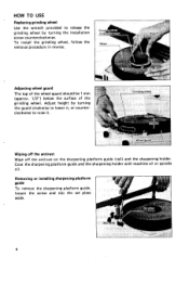
... guide, loosen the screw and slip the set plate aside. 6 To install the grinding wheel, follow the removal procedure in reverse. HOW TO USE Replacing grinding wheel Use the wrench provided to release the grinding wheel by turning the guard clockwiseto lower it, or counterclockwise to raise it. Adjusting wheel guard The...
... guide, loosen the screw and slip the set plate aside. 6 To install the grinding wheel, follow the removal procedure in reverse. HOW TO USE Replacing grinding wheel Use the wrench provided to release the grinding wheel by turning the guard clockwiseto lower it, or counterclockwise to raise it. Adjusting wheel guard The...
Owners Manual
Page 7
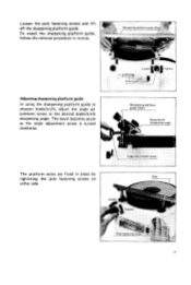
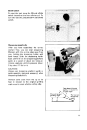
Sharpening platform guide (Rail) The platform poles are fixed in reverse. To install the sharpening platform guide, follow the removal procedure in place by tightening the pole fastening screws on Pole either side. 7 Loosen the pole fastening screws and lift off the sharpening platform guide. Adjusting sharpening platform guide In using the sharpening platform guide to sharpen blade/knife, adjust the angle adjustment screw to the desired blade/knife sharpening angle. The bevel becomes acute as the angle adjustment screw is turned clockwise.
Sharpening platform guide (Rail) The platform poles are fixed in reverse. To install the sharpening platform guide, follow the removal procedure in place by tightening the pole fastening screws on Pole either side. 7 Loosen the pole fastening screws and lift off the sharpening platform guide. Adjusting sharpening platform guide In using the sharpening platform guide to sharpen blade/knife, adjust the angle adjustment screw to the desired blade/knife sharpening angle. The bevel becomes acute as the angle adjustment screw is turned clockwise.
Owners Manual
Page 9
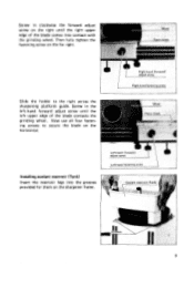
Screw in the left-hand forward adjust screw until the right upper edge of the blade contacts the grinding wheel. Installingcoolant reservoir (Tank) Insert the reservoir legs into contact with the grinding wheel. Now use all four fastening screws to the right across the sharpening platform guide. Slide the holder to secure the blade on the sharpener frame. 9 Then fully tighten the fastening screw on the far right. Screw in clockwise the forward adjust screw on the right until the left upper edge of the blade comes into the grooves provided for them on the horizontal.
Screw in the left-hand forward adjust screw until the right upper edge of the blade contacts the grinding wheel. Installingcoolant reservoir (Tank) Insert the reservoir legs into contact with the grinding wheel. Now use all four fastening screws to the right across the sharpening platform guide. Slide the holder to secure the blade on the sharpener frame. 9 Then fully tighten the fastening screw on the far right. Screw in clockwise the forward adjust screw on the right until the left upper edge of the blade comes into the grooves provided for them on the horizontal.
Owners Manual
Page 10
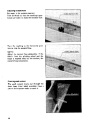
Adjusting coolant flow Put water in the coolant reservoir. Turn the knob so that the marking i s positioned vertically to catch it. 10 NOTE : Adjust the coolant flow adequately. Have a pan or drain system ready to make the coolant flow. Draining used coolant The used coolant drains out through the drain hose (vinyl tube) provided. If the debris from the grinding wheel and the blade is washed away by the coolant, the coolant flow is excessive. r Turn the marking to stop the coolant flow. tion to the horizontal posi-
Adjusting coolant flow Put water in the coolant reservoir. Turn the knob so that the marking i s positioned vertically to catch it. 10 NOTE : Adjust the coolant flow adequately. Have a pan or drain system ready to make the coolant flow. Draining used coolant The used coolant drains out through the drain hose (vinyl tube) provided. If the debris from the grinding wheel and the blade is washed away by the coolant, the coolant flow is excessive. r Turn the marking to stop the coolant flow. tion to the horizontal posi-
Owners Manual
Page 11
... begin sharpening. To turn the tool off, press the OFF side of the tool. Slide the sharpening holder back and forth on it. CAUTION : Always use sharpening platform guide or guide assembly (optional accessory) when sharpening bladdknife. Switch action To start the tool, press the ON side of the switch located...
... begin sharpening. To turn the tool off, press the OFF side of the tool. Slide the sharpening holder back and forth on it. CAUTION : Always use sharpening platform guide or guide assembly (optional accessory) when sharpening bladdknife. Switch action To start the tool, press the ON side of the switch located...
Owners Manual
Page 13
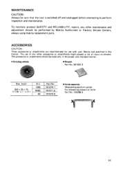
The accessories or attachments should be used only in the proper and intended manner. 0 Grinding wheels Wrench Part No. 341 391 - 3 Size (mm) I Grit I Part No. 200x25~75 (7-7/8" x 1" x 3") 741074-9 Guide ...and RELIABILITY, repairs, any other maintenance and adjustment should be performed by Makita Authorized or Factory Service Centers, always using makita replacement parts. The use with your Makita tool specified i n this manual. ACCESSOR IES CAUTION : These accessories or attachments are recommended for use of any other accessories or attachments might present a risk of injury ...
The accessories or attachments should be used only in the proper and intended manner. 0 Grinding wheels Wrench Part No. 341 391 - 3 Size (mm) I Grit I Part No. 200x25~75 (7-7/8" x 1" x 3") 741074-9 Guide ...and RELIABILITY, repairs, any other maintenance and adjustment should be performed by Makita Authorized or Factory Service Centers, always using makita replacement parts. The use with your Makita tool specified i n this manual. ACCESSOR IES CAUTION : These accessories or attachments are recommended for use of any other accessories or attachments might present a risk of injury ...
Owners Manual
Page 16
... defects from workmanship and materials for the period of ONE YEAR from state to you . IN NO EVENT SHALL MAKITA BE LIABLE FOR ANY INDIRECT, INCIDENTAL OR CONSEQUENTIAL DAMAGES FROM THE SALE OR USE OF THE PRODUCT. N Should any trouble develop during this one of incidental or consequential damages, so the above...
... defects from workmanship and materials for the period of ONE YEAR from state to you . IN NO EVENT SHALL MAKITA BE LIABLE FOR ANY INDIRECT, INCIDENTAL OR CONSEQUENTIAL DAMAGES FROM THE SALE OR USE OF THE PRODUCT. N Should any trouble develop during this one of incidental or consequential damages, so the above...
Parts Breakdown
Page 1
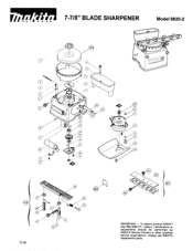
To assure product SAFETY and RELIABILITY. Always use MAKITA replacement parts. r r 7-7/8" BLADE SHARPENER Model 9820-2 01-96 IMPORTANT - repairs, maintenance or adjustments should be performed by MAKITA Service Centers or other qualified service organizations.
To assure product SAFETY and RELIABILITY. Always use MAKITA replacement parts. r r 7-7/8" BLADE SHARPENER Model 9820-2 01-96 IMPORTANT - repairs, maintenance or adjustments should be performed by MAKITA Service Centers or other qualified service organizations.
Parts Breakdown
Page 2
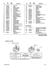
Used Description 1 271235-2 1 LOCK NUT 2 412033-7 1 TUBE 3 411429-9 1 WHEEL COVER 4 911231-5 2 SCREW M5X20 5 341392-1 2 SET PLATE 6 251847-7 2 KNOB M6X31 8 912002-3 2 C.H.SCREW M3X6 9 651502-5 1 SWITCH 10 645314-6...No. Fig. Part Qty. Fig. DESCRIPTION 17 Frame 52 Washer 1 0 TYPE 1 PART# 155220-2 (Discontinued) TYPE 2 PART# 151274-7 PART# 267040-3 (2 ea.) (See Service Change 2) 2 MODEL 9820-2 01-96 Used Description 33 941251-5 2 WASHER 10 34 921551-9 2 H.BOLT MIOX30 35 tt 1 UNDERCOVER 36 t* 0 SCREW 37 252619-3 1 NUT M I 6 38 256712-5 1 PIN 6 39 325540-0 1 SUB ...
Used Description 1 271235-2 1 LOCK NUT 2 412033-7 1 TUBE 3 411429-9 1 WHEEL COVER 4 911231-5 2 SCREW M5X20 5 341392-1 2 SET PLATE 6 251847-7 2 KNOB M6X31 8 912002-3 2 C.H.SCREW M3X6 9 651502-5 1 SWITCH 10 645314-6...No. Fig. Part Qty. Fig. DESCRIPTION 17 Frame 52 Washer 1 0 TYPE 1 PART# 155220-2 (Discontinued) TYPE 2 PART# 151274-7 PART# 267040-3 (2 ea.) (See Service Change 2) 2 MODEL 9820-2 01-96 Used Description 33 941251-5 2 WASHER 10 34 921551-9 2 H.BOLT MIOX30 35 tt 1 UNDERCOVER 36 t* 0 SCREW 37 252619-3 1 NUT M I 6 38 256712-5 1 PIN 6 39 325540-0 1 SUB ...
Parts Breakdown
Page 3
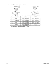
DESCRIPTION 31 Motor 35 Under Cover 36 Screw 52 Washer TYPE 1 PART# 6 2 9 5 10-4 (Discontinued) PART# 3425 16-2 (Discontinued) PART# 91 1104-2 M4x6 (Use 4 ea.) PART# 267040-3 (Discontinued) TYPE 2 PART# 629644-3 PART# 344030-4 PART# 91 1108-4 M4x8 (Use 3 ea.) ____-------- 01-96 3 MODEL 9820-2 2 ) Change on Motor from S/N 30,058E. FIG.
DESCRIPTION 31 Motor 35 Under Cover 36 Screw 52 Washer TYPE 1 PART# 6 2 9 5 10-4 (Discontinued) PART# 3425 16-2 (Discontinued) PART# 91 1104-2 M4x6 (Use 4 ea.) PART# 267040-3 (Discontinued) TYPE 2 PART# 629644-3 PART# 344030-4 PART# 91 1108-4 M4x8 (Use 3 ea.) ____-------- 01-96 3 MODEL 9820-2 2 ) Change on Motor from S/N 30,058E. FIG.


